
Guardrail-Style Plug-In Rack Load Testing and Three-Layer Stacking
derack
Technical case study of product 130013845: guardrail-form plug-in vertical racking load tested at 1.2 t per rack, plus two- and three-layer stacking, forklift handling and fork unloading tests.
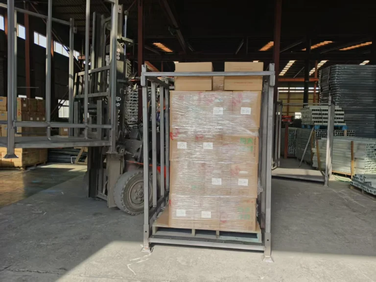
Guardrail-Style Plug-In Rack Load Testing and Three-Layer Stacking
How a guardrail-form plug-in vertical racking unit — built from a base, two joined side column plates and two connecting rods — was verified with a 1.2 t per-rack load test, two- and three-layer stacking, dynamic forklift handling, fork unloading, pre-coating trial assembly, dimensional inspection and a 160 kg weight check.

Guardrail-Style Plug-In Rack Load Testing and Three-Layer Stacking
For a plug-in rack, the individual components are rarely the only consideration. The more demanding question is what happens when several units are loaded, handled and stacked together.
Product 130013845 was developed around that requirement. Its side uprights are connected to form a continuous column plate with a guardrail-like appearance, and two connecting rods provide additional fixation. The stated purpose of this arrangement is to improve stability when the racks are stacked.
The customer expected to stack the racks three levels high. The production programme therefore included:
a single-rack load test;
two- and three-layer stacking tests;
a dynamic forklift-handling test;
a fork-unloading test;
a trial assembly before coating;
dimensional measurements; and
a completed-product weight check.
The review covered a batch of 21 plug-in rack units manufactured at the Hebei factory.
This product was not tested only as an individual rack. Its production review examined how the unit behaved with its intended load, how several loaded units interacted in a stack and whether the product could be assembled correctly before the final coating was applied.
1. Production and Testing Review at a Glance
| Item | Recorded Detail | Significance |
|---|---|---|
| Product code | 130013845 | Product covered by the production review |
| Production location | Hebei factory | Manufacturing and testing location |
| Batch quantity | 21 plug-in rack units | Number of complete rack units included in the reviewed batch |
| Main structural elements | Base, two side column plates and two connecting rods | Principal construction described in the presentation |
| Side construction | Two uprights connected into one column plate | Creates a more continuous and rigid side structure |
| Visual result | Guardrail-form side panel | Recognizable appearance produced by the structural arrangement |
| Connecting rods | Two rods provide additional fixation | Improve the stability of the connected upright structure |
| Design objective | Improve stability during stacking | The customer intended to stack the racks three levels high |
| Specified working load per rack | 1.2 t | Load used as the basis of the production test |
| Test ballast | Bagged plastic powder | Factory material used as the test load |
| Ballast weight | 25 kg per bag | Recorded packaging weight |
| Number of bags per rack | 48 bags | Produces the specified working load |
| Total applied load | 1,200 kg, equivalent to 1.2 t | Matches the load stated in the drawing |
| Stacking test | Two- and three-layer configurations | Verified the customer’s intended stacking arrangement |
| Forklift handling | Two loaded layers lifted together during the test | Recorded as a deviation from the correct procedure |
| Correct stacking method | One unit inserted at a time | The procedure stated by the presenter |
| Fork unloading | Test footage from the stacked arrangement | Verifies removal with a forklift |
| Pre-coating check | Complete trial assembly before powder coating | Confirms that the components fit correctly |
| Final finish | Green powder coating | Applied after the pre-coating assembly check |
| Measured product weight | 160 kg | Compared with a theoretical weight of slightly more than 150 kg |
| Weight interpretation | Heavier than theoretical | Presented as evidence of full-size, full-thickness material |
| Certified stack rating and overall dimensions | Not disclosed | Must be obtained from the released engineering documents |
The source describes the reviewed quantity as “21 plug-in racks.” Because the surrounding discussion repeatedly refers to individual racks and shows multiple units in the stacking tests, the quantity is treated here as 21 complete rack units—not 21 components within one rack.
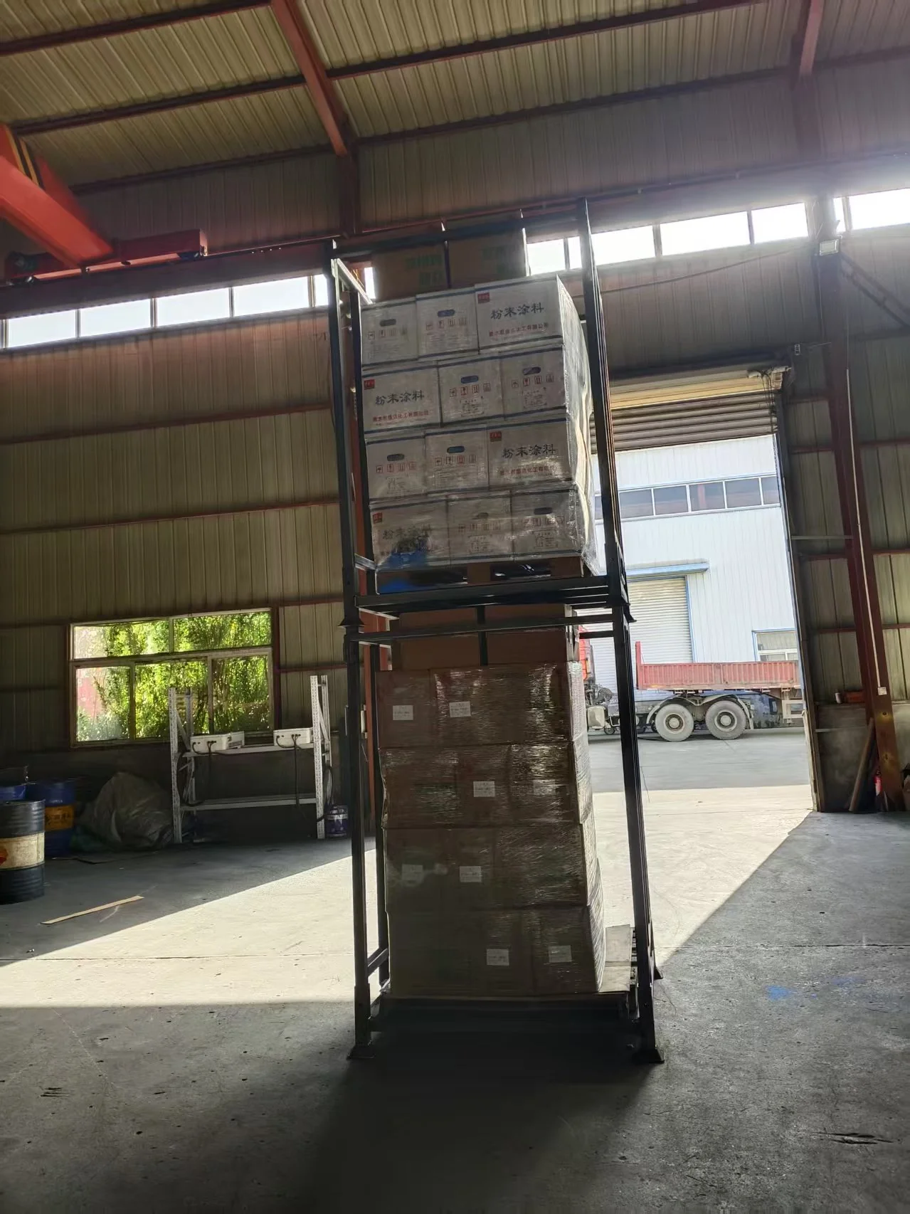
2. Why the Side Structure Was Changed
The customer’s requirement was not limited to supporting a load on one rack. The intended arrangement required three racks to be stacked vertically.
That requirement changes the structural problem.
| Customer Requirement | Structural Consequence |
|---|---|
| Carry 1.2 t on an individual rack | The base, column plates and connections must support the working load |
| Stack three units vertically | Each lower unit must also carry the units above it |
| Maintain stability in the completed stack | The side structure must resist lateral distortion and racking |
| Permit plug-in assembly | The upright-to-base interface must remain functional during installation |
| Support removal with a forklift | The plug-in connections must remain secure during dynamic handling |
| Reduce shipping volume | The rack must retain its plug-in and removable construction |
A conventional rack with separate uprights can perform adequately as an individual unit while remaining less suitable for a high stack. Connecting the uprights changes the side from two independently supported members into a more continuous structural panel.
Stacking is not simply a matter of placing one rack on top of another. The lower rack becomes part of a larger structural system, and frame rigidity becomes as important as the individual rack’s load capacity.

3. The Guardrail-Form Column-Plate Design
The principal structural feature is the way the side uprights are connected.
3.1 From Separate Uprights to One Column Plate
The two uprights on each side are joined together to form a single column plate. The resulting side resembles a guardrail.
| Structural Arrangement | Behaviour in the Intended Stack |
|---|---|
| Two separate uprights | Each upright depends more heavily on its individual base connection for lateral stability |
| Two uprights connected into one column plate | The side behaves as a more continuous panel with a shared load path |
| Continuous column plate | Greater resistance to sideways distortion |
| Connecting rods | Add further fixation to the connected structure |
| Guardrail-form appearance | Visible result of the structural arrangement |
| Functional benefit | Improved stability when units are stacked |
The guardrail appearance is therefore not merely a visual styling choice. It is the visible result of a structural decision intended to improve stacked-rack stability.
The guardrail form should be specified for the structural reason it exists. Its appearance helps identify the product, but the continuous column plate provides the functional advantage.
3.2 The Two Connecting Rods
Two connecting rods complete the upright arrangement.
| Connecting-Rod Function | Structural Effect |
|---|---|
| Additional fixation | Holds the connected upright elements in their intended relationship |
| Increased lateral restraint | Helps the column plate retain its geometry under combined loading |
| Connection security | Reduces the likelihood of separation or excessive movement at the fixed interface |
| Stacking contribution | Adds stability to the assembled side structure |
| Assembly role | Complements the joined column-plate arrangement |
| Detailed specification | Not disclosed; must be confirmed on the released drawing |
The rods provide an economical increase in stiffness without requiring the customer to use a completely different rack platform.
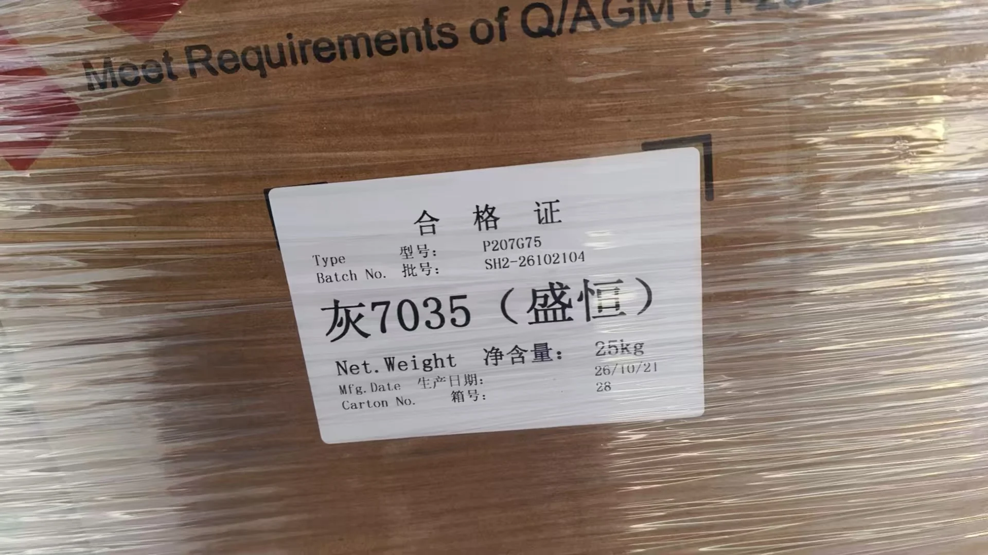
4. Important Distinction: Per-Rack Load Is Not the Same as Stack Load
The source states a working load of 1.2 t per rack and also records a three-layer stacking test. These are two different engineering conditions.
| Load Concept | Meaning |
|---|---|
| Individual-rack working load | The material load supported by one rack in its normal operating position |
| Single-rack load test | Verification of one rack under its stated working load |
| Lower-rack load in a stack | The rack’s own load plus the loads of all racks above it |
| Complete-stack capacity | The total load and stability capability of the connected stack |
| Structural connection demand | The forces transferred through the base and plug-in interfaces of the lower units |
If every rack in the three-layer test carried 1.2 t, the aggregate payload carried by the bottom rack would be:
1.2 t in the bottom rack + 1.2 t in the middle rack + 1.2 t in the top rack = 3.6 t of payload, before accounting for the self-weight of the upper racks.
The source does not disclose the approved bottom-rack rating, stack rating or acceptance criterion. This calculation should therefore not be presented as a certified capacity. It demonstrates why the per-rack working load cannot be used by itself to establish the permitted three-layer stack load.
| Required Engineering Confirmation | Why It Matters |
|---|---|
| Approved per-rack working load | Establishes the normal material capacity |
| Approved bottom-rack capacity in a stack | Governs the cumulative load on the lowest unit |
| Approved maximum stack height | Establishes how many units may be stacked |
| Base and connection stack rating | Controls the load path between levels |
| Forklift and installation limitations | Determine whether the approved sequence can be performed safely |
| Site floor and stability requirements | Affect the stability of the completed stack |
The 1.2 t figure applies to the stated individual-rack load condition. Any three-layer stack must be approved against its own cumulative-load and connection requirements.
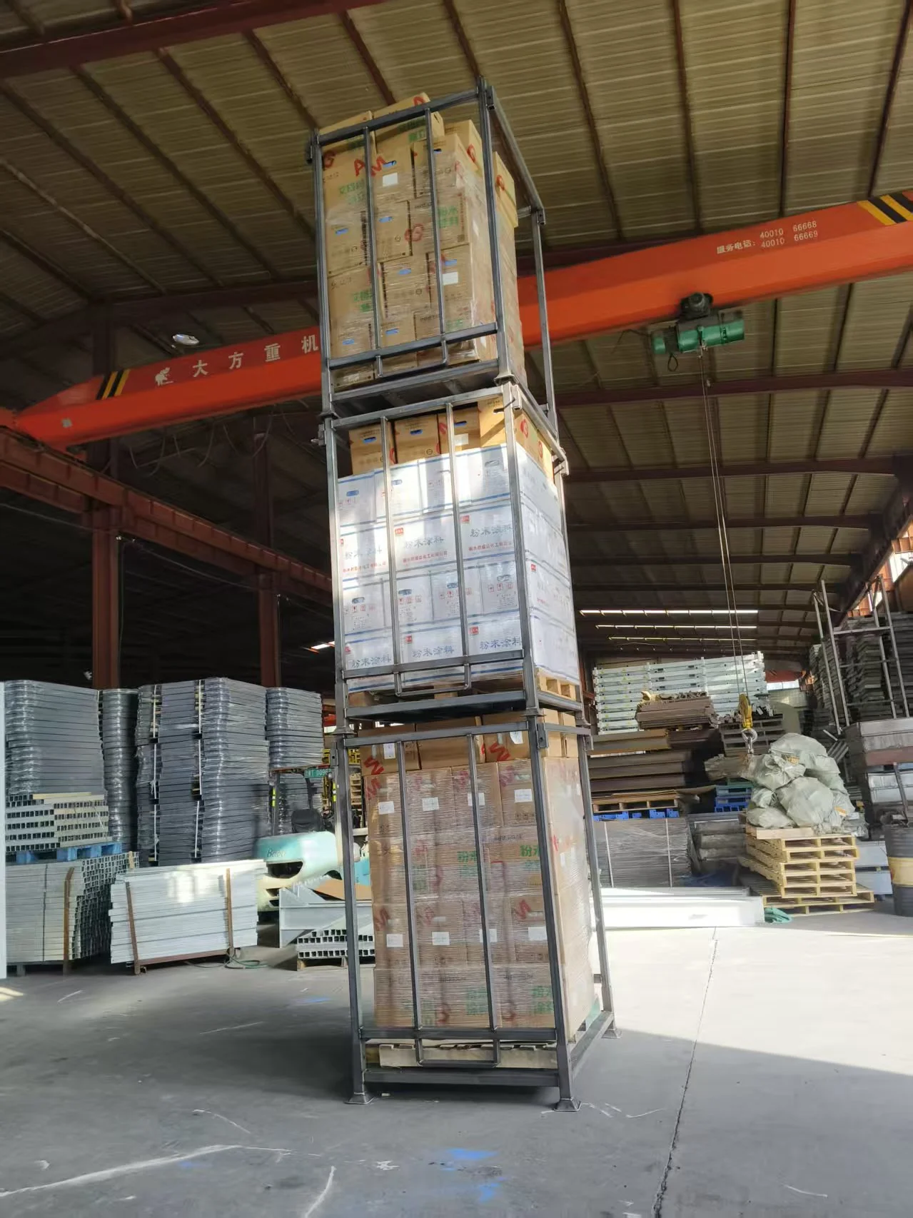
5. Load Test with Factory Ballast
The load test used material already available at the Hebei factory: bagged plastic powder.
5.1 The Applied Load
| Test-Load Element | Recorded Detail |
|---|---|
| Test material | Plastic powder in bags |
| Weight per bag | 25 kg |
| Bags placed on each rack | 48 |
| Total applied load | 48 × 25 kg = 1,200 kg |
| Equivalent load | 1.2 metric tons |
| Relationship to the drawing | The presenter confirmed that it matched the specified drawing load |
| Test condition | Load applied to a rack before the stacking tests |
| Load retained during stacking | The stacking test was performed after the racks had been loaded |
5.2 Why Factory Material Was Used
Using bagged material provided a practical and repeatable test load without requiring special calibrated test weights.
| Test-Material Characteristic | Benefit |
|---|---|
| Standard 25 kg bags | Makes the total load easy to calculate and reproduce |
| Distributed across the rack | More representative than a concentrated point load |
| Available production stock | Allows testing without purchasing a dedicated test load |
| Realistic package geometry | Approximates the footprint and distribution of stored goods |
| Repeatable quantity | The same 48-bag arrangement can be used on each tested rack |
| Practical evidence | Supports visual inspection of deformation and connection behaviour |
5.3 What the Load Test Examined
| Inspection Criterion | Potential Failure Detected |
|---|---|
| Base deformation | Excessive bending or distortion of the supporting base |
| Column-plate deformation | Side movement or bowing under the working load |
| Connecting-rod behaviour | Loosening, movement or inadequate fixation |
| Plug-in connections | Separation or excessive movement at the base interfaces |
| Weld and fabrication condition | Cracking, opening or other visible fabrication defects |
| Overall rack geometry | Settlement, skew or loss of the intended shape |
| Stability before stacking | Weakness that might be concealed by the later stacked configuration |
The source presents the load test as a physical verification through photographs and video. It does not disclose a numerical deflection limit, strain measurement or formal pass/fail threshold. Those values must come from the released engineering and acceptance documentation.
The test reproduces the intended working condition: 48 bags of 25 kg material, giving exactly the 1.2 t load identified in the drawing.
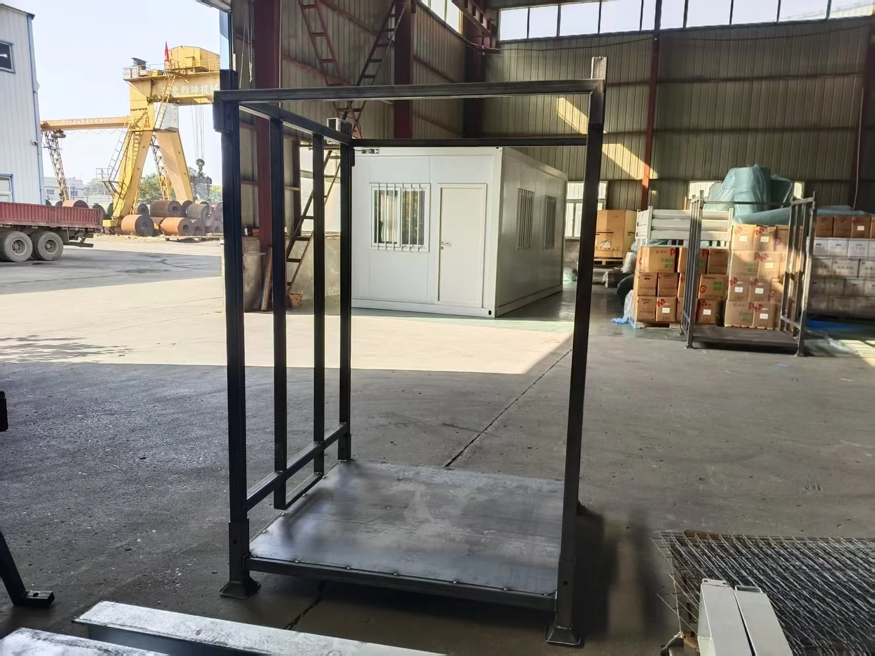
6. One-, Two- and Three-Layer Stacking Tests
After loading, the racks were stacked and the configurations recorded.
| Stacking Stage | Recorded Condition | Purpose |
|---|---|---|
| One layer | Loaded rack in the single-unit condition | Baseline before combining units |
| Two layers | Loaded racks stacked together | Verifies the intermediate stacked condition |
| Three layers | Loaded racks stacked to the customer’s intended height | Demonstrates the maximum arrangement discussed |
| Stacking video | Operation recorded on video | Preserves the assembly sequence and observed behaviour |
| Post-test photographs | One-, two- and three-layer configurations recorded | Provides visual evidence of the completed stacks |
| Stability observation | Overall stability described as very good during the dynamic lift | Recorded under the non-standard method discussed below |
6.1 What the Stacking Test Added
The single-rack load test and the stacking test answer different questions.
| Test | Question It Answers |
|---|---|
| Individual load test | Can one rack hold its specified working load without unacceptable deformation? |
| Two-layer stack | Can one rack remain stable while carrying another loaded rack? |
| Three-layer stack | Can the complete stack remain stable under the intended arrangement? |
| Fork unloading | Can a rack be disengaged and removed from the stack with a forklift? |
| Dynamic lifting | How does the frame behave while being moved by a forklift? |
A rack that passes the individual load test may still behave differently when it forms the bottom of a multi-level stack.
The individual rack test verifies capacity. The stacking test verifies the system.

7. Important Safety Record: A Non-Compliant Forklift Movement
During the stacking test, the factory used a handling sequence that the presenter explicitly identified as non-compliant.
This should be documented accurately and must not be presented as the recommended operating method.
7.1 What Was Actually Performed
| Step | Action Recorded in the Test |
|---|---|
| 1 | A two-layer stack had already been assembled and loaded |
| 2 | The two layers were lifted together by forklift |
| 3 | The combined two-layer assembly was inserted downward onto a single rack |
| 4 | The dynamic lifting and overall stability were observed and recorded on video |
Although the stack remained stable during the movement, the presenter stated that the method should not be used.
7.2 Why the Deviation Was Used
The stated reason was a limitation of the forklift available at the Hebei factory.
| Handling Requirement | Available Condition |
|---|---|
| The normal procedure requires one rack to be lifted above the existing stack | The factory forklift’s lifting height was considered insufficient for that movement |
| A direct one-unit insertion was therefore not available using that forklift | Two loaded layers were lifted together and inserted onto one rack |
| The workaround was intended to complete the three-layer demonstration | It was not the approved operating procedure |
7.3 The Correct Stacking Method
The presenter clearly identified the correct sequence.
| Stack Height | Correct Method |
|---|---|
| Two layers | Place one rack onto one rack |
| Three layers | Place one rack, then another rack, and then the third rack—one unit at a time |
| Method explicitly rejected | Building a three-layer stack by placing one rack and then inserting a two-rack block together |
The two-unit lift may provide useful test evidence, but it does not become an approved operating method because the rack remained stable.
7.4 Why This Distinction Matters
| Lesson | Explanation |
|---|---|
| Equipment capability is part of the operating method | A procedure may be correct in principle but impossible with the available forklift |
| Stability in one test does not authorize unsafe practice | A successful observation cannot replace the approved method |
| The lower rack receives a much greater force | Lifting two loaded layers together creates a demanding combined condition |
| Site training must follow the approved sequence | The correct method should appear in the operating instructions |
| Handling equipment must be selected accordingly | The forklift’s rated capacity and lifting height must match the installation sequence |
| The test record should remain honest | Both the deviation and the correct method belong in the production record |

8. Fork-Unloading Test
The production videos also included a fork-unloading test from the stacked arrangement.
| Test Aspect | Recorded Purpose |
|---|---|
| Fork engagement | Verifies that the forklift can engage the rack while it is stacked |
| Unloading movement | Tests removal of a rack from the completed arrangement |
| Dynamic condition | Introduces the concentrated forces associated with fork engagement and lifting |
| Connection behaviour | Confirms that the plug-in interfaces remain secure during withdrawal |
| Evidence | Video recorded |
| Quantitative acceptance result | Not disclosed in the source material |
The fork-unloading test is different from the load test and from the stacking operation. It checks the product’s behaviour when a rack is being disengaged and removed rather than inserted or held under load.
The forklift must be able to perform the entire operating cycle—not only the loading and stacking movements shown in the production record.
9. Trial Assembly Before Powder Coating
One of the most valuable production checks was carried out before the final coating.
9.1 Why the Product Was Assembled First
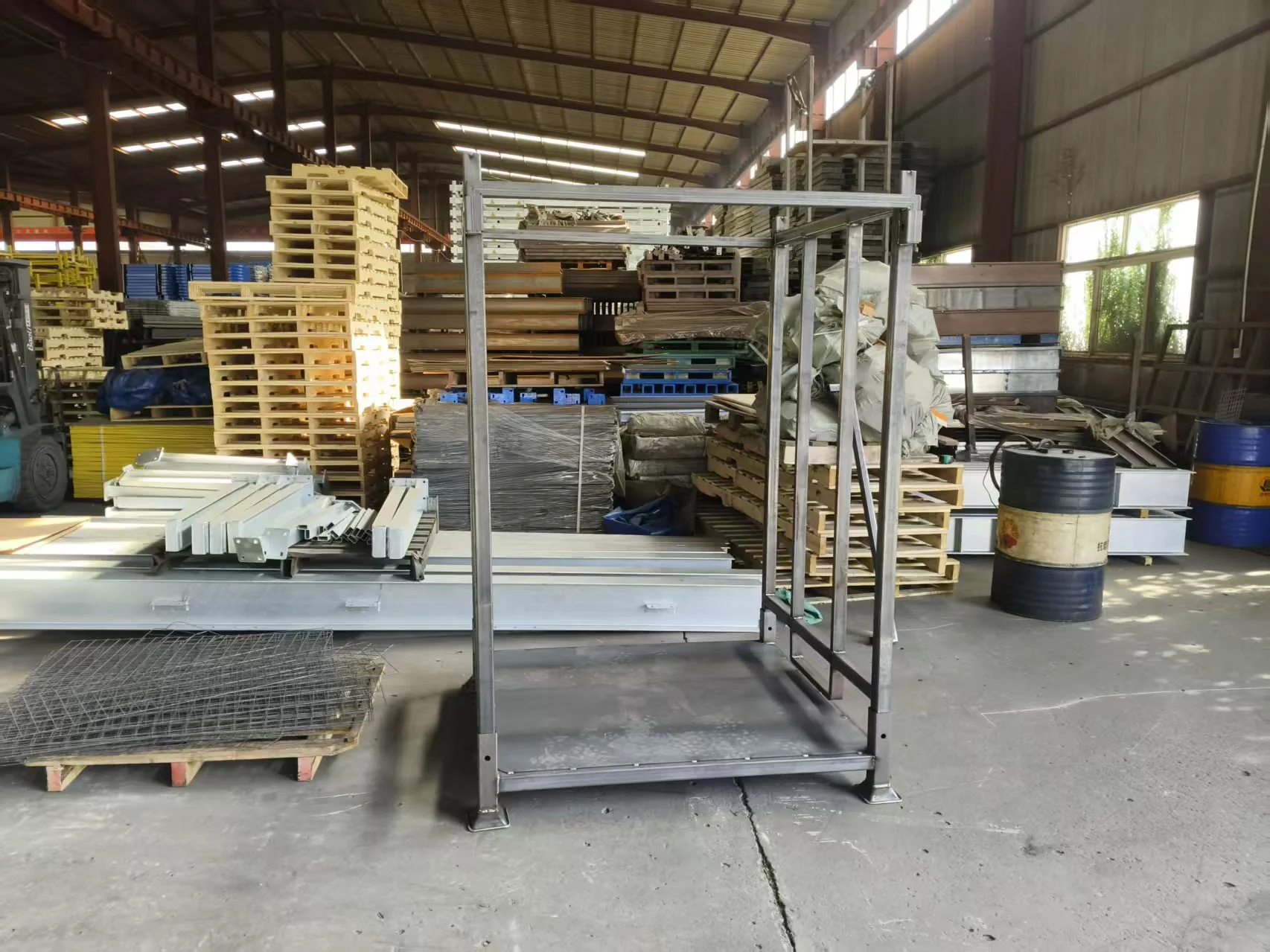
The complete rack was trial-assembled on bare components to confirm that it did not have a dimensional or fit problem.
| Production Stage | Recorded Action | Purpose |
|---|---|---|
| Before coating | Complete trial assembly performed | Verify that all components fit together correctly |
| During assembly | Interfaces and component relationships checked | Detect interference, dimensional inconsistency or assembly difficulty |
| After the check | Components separated for coating | Allow the normal component-level powder-coating process |
| After coating | Green powder coating applied | Produce the final appearance |
| Finished-product record | Assembled appearance photographed | Preserve the approved product configuration |
9.2 Why Coating Before Assembly Is Less Efficient
| Sequence | Consequence of a Fit Error |
|---|---|
| Assemble first, then coat | Fit issues are found on bare components and can be corrected before finishing |
| Coat first, then assemble | A dimensional error is discovered only after the coating has been applied |
| Correction after coating | May require removal, rework and recoating of the affected parts |
| Trial assembly | Confirms functional fit while correction remains straightforward and economical |
The green powder coating represents the final appearance, but it was not intended to conceal an unresolved dimensional problem.
Trial assembly before coating converts a hidden fit error into a visible workshop error—one that can still be corrected at the lowest cost.
10. Dimensional Inspection
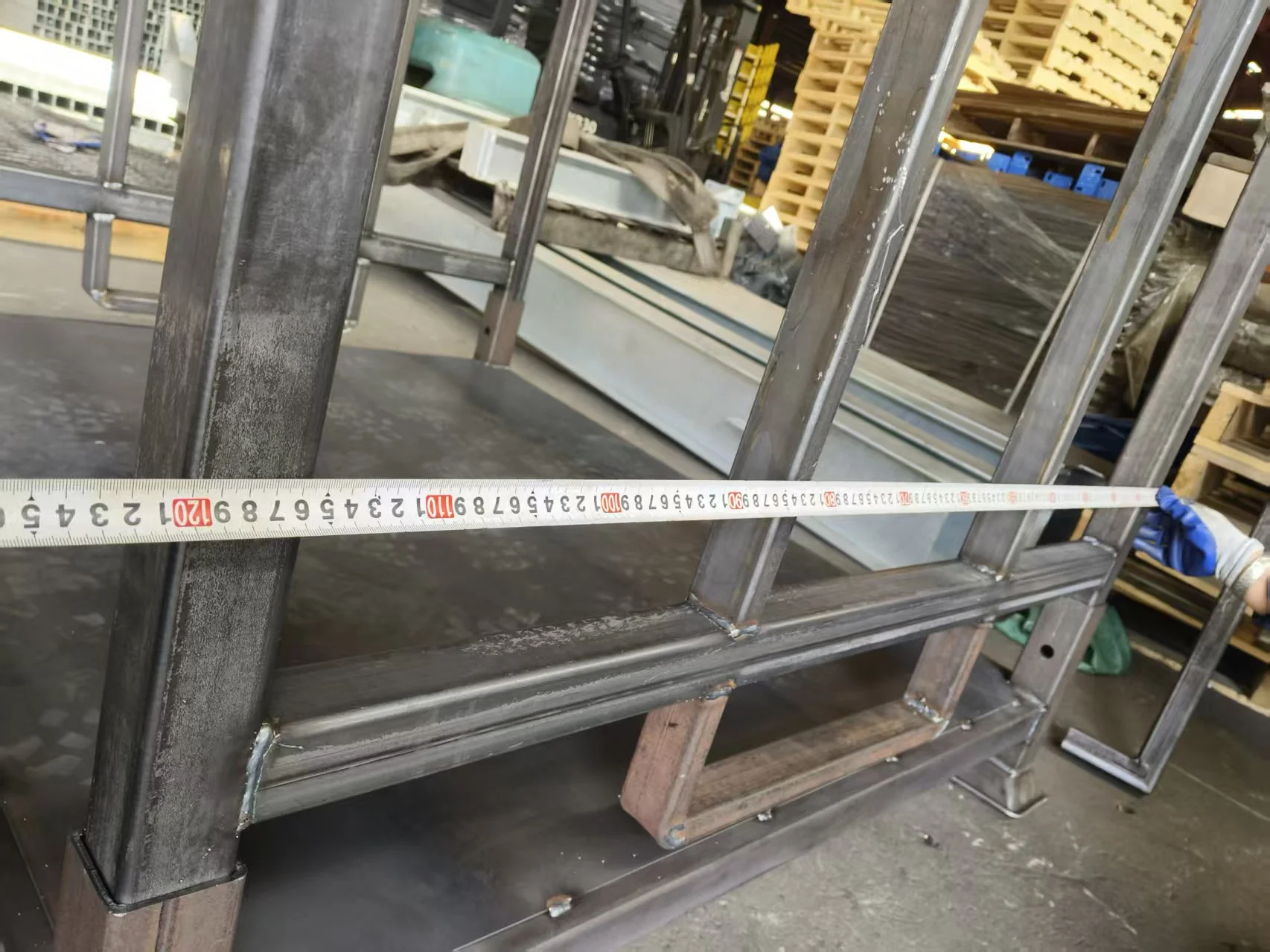
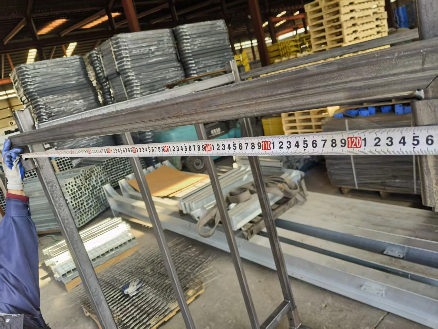
The production record included dimensional measurements of the completed rack.
| Inspection Item | Purpose | Recorded Result |
|---|---|---|
| Overall rack dimensions | Confirm that the physical product matches the released drawing | Exact values not stated in the transcript |
| Assembly fit | Verify that the base, column plates and rods work together | Trial assembly completed successfully |
| Interface geometry | Confirm that the plug-in components engage correctly | Functional fit demonstrated |
| Stacking geometry | Confirm that units can be combined in the intended configuration | Two- and three-layer configurations demonstrated |
| Drawing comparison | Identify any difference between the design and production product | Formal tolerance results not stated |
The photographs should be retained with the production record so that the measured values can be recovered and matched to the released drawing.
A successful trial assembly is strong functional evidence of fit, but it does not replace the drawing tolerances and formal dimensional inspection record.

11. Completed-Product Weight Verification
The completed product was weighed.
| Measurement | Recorded Value |
|---|---|
| Actual product weight | 160 kg |
| Theoretical weight | Slightly more than 150 kg |
| Difference | Actual weight exceeded the theoretical reference |
| Presenter’s interpretation | The material was full-size and full-thickness |
| Material compliance | Supported by the presenter’s weight comparison |
| Formal weight tolerance | Not disclosed |
11.1 How to Interpret the Result
A heavier product can be consistent with full nominal sections and adequate wall thickness.
| Possible Explanation | Assessment in Relation to the Source |
|---|---|
| All sections were manufactured at full nominal size | Consistent with the presenter’s interpretation |
| Steel was supplied at full nominal thickness | Consistent with the presenter’s interpretation |
| Additional welds or attachments increased the weight | Possible, but not stated |
| Component weight was underestimated in the theoretical calculation | Possible, but not stated |
| Incorrect heavier material was used | Possible in principle, but not supported by the source |
| Conclusion to publish | The measured weight was presented as evidence that the material was not undersized or under-thickness |
11.2 What Weight Verification Does and Does Not Prove
| The Weight Check Supports | It Does Not by Itself Prove |
|---|---|
| Material was not systematically undersized | That every component is the correct grade |
| Full nominal sections were likely used | That the certified load capacity has been verified |
| The bill of materials was substantially delivered | That every dimensional tolerance is satisfied |
| Production material usage is broadly consistent with the drawing | That the coating thickness or finish is correct |
| A useful early-warning production check | That every connection satisfies the released specification |
The weight check is an aggregate indicator and should be used alongside the dimensional inspection, trial assembly, load test and stacking test.
A product heavier than its theoretical weight is a useful production signal, but it is not a substitute for material certificates, dimensional inspection and physical testing.
12. Consolidated Production and Test Matrix
| No. | Stage | Check | Method | Recorded Result or Requirement |
|---|---|---|---|---|
| 1 | Structure review | Confirm product configuration | Visual and drawing comparison | Base, two joined side column plates and two connecting rods |
| 2 | Structure review | Confirm stacking-oriented design | Visual inspection | Connected uprights and rods improve stacking stability |
| 3 | Pre-coating | Complete trial assembly | Manual assembly | Confirmed that the product had no dimensional fit problem |
| 4 | Pre-coating | Dimensional inspection | Direct measurement | Exact readings not stated in the transcript |
| 5 | Pre-coating or final check | Product self-weight | Weighing | 160 kg measured |
| 6 | Weight review | Compare actual and theoretical weight | Production calculation | Actual weight exceeded the theoretical figure of slightly over 150 kg |
| 7 | Load test | Apply working load | 48 bags of plastic powder at 25 kg each | 1,200 kg applied per rack |
| 8 | Load test | Confirm load equivalence | Compare with drawing load | Applied load matched the drawing load |
| 9 | Load test | Inspect individual rack | Visual inspection and video | Load test completed before stacking |
| 10 | Stacking test | One-layer reference | Loaded rack | Single-unit condition recorded |
| 11 | Stacking test | Two-layer stack | Stack loaded units | Two-layer configuration completed and recorded |
| 12 | Stacking test | Three-layer stack | Stack loaded units | Customer’s intended maximum configuration completed |
| 13 | Stacking test | Record assembly sequence | Video | Stacking behaviour preserved |
| 14 | Dynamic handling | Lift two loaded layers together | Forklift | Overall stability described as very good |
| 15 | Dynamic handling | Identify method deviation | Procedure review | Explicitly identified as non-compliant |
| 16 | Dynamic handling | State correct method | Presenter instruction | One rack inserted at a time |
| 17 | Fork unloading | Remove rack from stacked arrangement | Forklift test | Test footage recorded |
| 18 | Final finish | Apply green powder coating | Coating process | Final appearance specified |
| 19 | Final inspection | Confirm assembled appearance and condition | Visual inspection | Production photographs retained |
| 20 | Release | Retain complete production evidence | Document control | Photographs, videos, measurements and test records form the production record |
Member sections, dimensional tolerances, the certified per-rack and stack ratings, connection specifications, coating details and the exact recording date were not disclosed and must be obtained from the released project documentation.
13. Eight Lessons from the 130013845 Production Review
1. Stacking Changes the Design
A rack intended for three levels is not simply a single rack placed three times. The connected side structure and lower-unit load path must be designed for the stack.
2. A Continuous Column Plate Improves Lateral Rigidity
Joining the side uprights reduces reliance on two independent base connections to maintain the side geometry.
3. Connecting Rods Are Efficient Added Stiffness
Two rods contribute meaningfully to the stability of the joined side structure at relatively little material cost.
4. Test the Individual Rack Before the Stack
The single-rack load test was completed before the stacking sequence. A stack should not be used to discover a weakness that could have been identified in the individual unit.
5. Per-Rack Load Does Not Define Stack Capacity
The bottom rack in a fully loaded three-layer arrangement carries the loads of both racks above it. The cumulative case must be approved separately.
6. A Successful Deviation Is Still a Deviation
The two-unit forklift lift remained stable, but the presenter correctly identified it as non-compliant. Good performance in a test does not replace the approved procedure.
7. Fit Is Cheaper to Verify Before Coating
The pre-coating trial assembly ensured that dimensional fit was checked while corrections were still easy, economical and free of coating-related rework.
8. Weight Is a Production Screen, Not a Certificate
The 160 kg measured weight supports the conclusion that the material was full-size and full-thickness. It complements, rather than replaces, the dimensional and physical tests.
14. Conclusion
Product 130013845 demonstrates how a stacking requirement can influence both the product structure and its production test programme.
Guardrail-Form Plug-In Construction
The rack comprises a base, two side column plates and two connecting rods. On each side, the two uprights are connected to form a single guardrail-form column plate. This makes the side structure more continuous and rigid, while the rods provide additional fixation.
The intended result is better stability when several racks are stacked. The guardrail appearance is therefore an indication of the structural concept rather than a purely decorative feature.
Verified 1.2-Tonne Working Load
Each rack was loaded with 48 bags of plastic powder weighing 25 kg each, producing an applied load of exactly 1,200 kg, matching the load identified in the drawing.
The single-rack load test was completed before the stacking tests, so that the individual unit’s capacity was checked before adding the loads of other units.
Two- and Three-Layer Stacking
The loaded racks were stacked in two- and three-layer configurations, with the sequence documented by photographs and video. The three-layer arrangement corresponds with the customer’s intended use.
Because the lowest rack carries the units above it, the 1.2 t individual working load cannot be used by itself to define the approved stack capacity.
A Documented Forklift Deviation
During the test, two loaded layers were lifted together and inserted onto a single rack because the factory forklift’s lifting height was insufficient for the standard movement. Although the presenter described the assembly’s stability as very good, the method was explicitly identified as non-compliant.
The correct method is to insert one rack at a time. That procedure belongs in the product instructions and site training.
Fork Unloading and Pre-Coating Verification
Fork-unloading footage was recorded from the stacked arrangement. Before the final green powder coating, the complete rack was also trial-assembled to confirm that no dimensional or fit problem existed.
160 kg Product Weight
The completed product weighed 160 kg, exceeding the theoretical figure of slightly more than 150 kg. The presenter interpreted this as confirmation that the material was full-size and full-thickness.
This production review shows what a stacking-led product looks like in practice: a joined and tied side structure, a load test that reproduces the drawing load, stacking tests at two and three levels, an honest record of a non-compliant forklift movement, and a fit check performed before the coating made any dimensional error permanent.
Send the working load, intended stack height and the handling equipment available on site. We will confirm the approved per-rack working load, the bottom-rack capacity in a stack and the installation sequence against the released engineering documents before a vertical storage rack system is specified. Contact Steel Pallet