
CRACK Fabric-Roll A-Frame Rack: Bolted Structure and Hollow Steel Roller
Technical breakdown of the CRACK fabric-roll A-frame rack: bolted and hinged A-frame, casters and fixed legs, front towing interface, bearing housings and a hollow steel roller with an optional 304 stainless surface.
CRACK Fabric-Roll A-Frame: A Bolted Rack Built Around a Hollow Steel Roller
A full structural breakdown of the CRACK rack: the base with casters and fixed legs, the front towing interface, the bolted and hinged A-frame, the bearing housings, the hollow drum roller, the optional 304 stainless contact surface, and the engineering items that still require formal closure before production release.
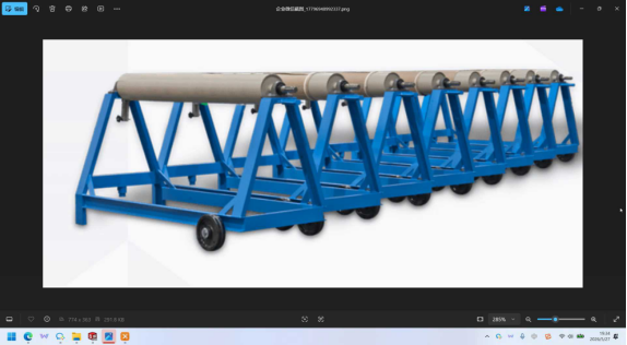
CRACK Product Structure: A Bolted A-Frame Fabric-Roll Rack with a Hollow Steel Roller
Not every storage product begins with a blank sheet. Many begin with an industry, a material and an awkward handling habit.
The CRACK was developed around the textile sector. It stores fabric rolls, referred to in Chinese as cloth rolls, and is intended for the printing and dyeing industry.
Its two Chinese working names—fabric-roll A-frame and printing-and-dyeing-plant A-frame—identify both the stored product and the industry it serves.
The supporting structure above the roller resembles the letter A, which explains the A-frame reference in both names.
Although the product looks relatively simple, its structure is based on three principal assemblies:
the base, which supports the complete product and provides ground contact;
the A-frame, which carries the roller and can be separated from the base for transport;
the roller, a hollow steel drum welded to its shaft and supported by bearing housings at both ends.
The CRACK combines a stable rolling base, an A-shaped support structure and a rotating hollow drum. Its practical value comes from how these three assemblies are connected and prepared for export.
Recommended hero image: approved 3D rendering showing a complete row of CRACK units in the operating position.
1. Product Structure at a Glance
| Item | Recorded Detail | Função |
|---|---|---|
| Produto | CRACK | Storage rack for fabric rolls used in the textile industry |
| Stored material | Fabric rolls or cloth rolls | Cylindrical, potentially contamination-sensitive textile goods |
| Target industry | Printing and dyeing | Intended customer sector and operating environment |
| Chinese working names | Fabric-roll A-frame and printing-and-dyeing-plant A-frame | Both identify the A-frame structure and fabric-roll application |
| Naming rationale | The upper support frame resembles the letter A | The product name reflects its actual load-bearing geometry |
| Configuration shown | A row containing multiple CRACK units | The structural explanation applies to one unit within the row |
| Design status | A 3D solid model has been completed | Further changes are expected, while the basic structure is retained |
| Main structural assemblies | Base, A-frame and roller | These form the complete product |
| Base function | Supports everything installed above it | Primary structural and mobility assembly |
| Base mobility | Caster wheels on one side and fixed support legs on the other | Maintains stability when parked and permits controlled towing |
| Front towing interface | Hollow tubular fitting | Receives a separate towing accessory |
| A-frame connection | Bolted to the base | Reduces the transport envelope for export shipments |
| Hinged transport arrangement | Hinge provided at the A-frame-to-base connection | Allows the A-frame to be folded down for shipment |
| Roller | Hollow drum with an end cap, welded to its shaft | Supports and rotates the fabric roll |
| Roller support | Bearing housing on each side | Supports the shaft and enables smooth rotation |
| Roller material option | 304 stainless steel may be specified | Reduces contamination risk for sensitive textile products |
| Lower frame members | Channel steel | Forms the structural frame beneath the rollers |
| Channel-section reference | Described as No. 10 channel, 100 mm high and 100 mm wide | Actual section dimensions and thickness must be confirmed on the released drawing |
The presentation does not disclose the overall dimensions, roller length or diameter, maximum roll weight, number of units in a complete row, coating specification, bolt specification, certified load rating or packing quantities. These details must be obtained from the released drawings and technical documentation.
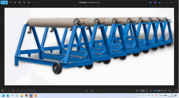
2. What the Product Name Reveals
The presenter began by explaining the two principal Chinese keywords. These are useful to anyone reading a specification or interpreting the product drawings.
2.1 The Two Chinese Keywords
| Original Chinese Name | English Equivalent | What It Reveals |
|---|---|---|
| Fabric-roll A-frame | Fabric-roll A-frame | The stored goods are fabric rolls and the supporting structure is A-shaped |
| Printing-and-dyeing-plant A-frame | Printing-and-dyeing-plant A-frame | The intended user is a printing or dyeing plant |
The names therefore communicate three points before a customer sees the physical product.
| Inference | Basis |
|---|---|
| The stored product is a fabric roll | The cloth-roll term appears in the primary keyword |
| The target industry is printing and dyeing | The printing-and-dyeing term appears in the second keyword |
| The A-frame is a defining structural element | The A-frame reference appears in both names |
2.2 Why the Letter “A” Is Used
The reason for the letter A is structural rather than decorative.
| Naming Element | Explanation Given in the Presentation |
|---|---|
| Letter A | The upper support frame resembles the letter A when viewed in profile |
| Location in the name | Included in both Chinese working names |
| Structural significance | The A-frame carries the roller assembly above the base |
| Layout significance | Its geometry establishes the roller orientation and the available loading space |
A product name that identifies both the stored material and its principal support structure makes technical communication much easier.
The A in A-frame describes the actual geometry of the load-bearing member. It is not merely a product-family label.
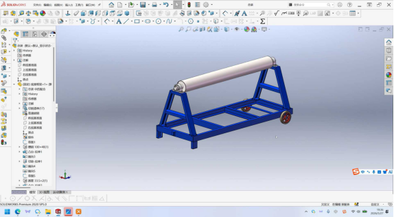
3. The Three Main Structural Assemblies
The product structure can be understood through three components.
| Componente | English Term | Primary Role | Main Subassemblies |
|---|---|---|---|
| Base | Base | Supports all components above it and provides ground contact | Caster wheels, fixed support legs, towing interface and lower frame |
| A-frame | A-frame | Carries the roller above the base | Bearing housings and the bolted and hinged connection to the base |
| Roller | Roller | Holds and supports the fabric roll | Hollow drum, end cap, shaft and bearing interfaces |
| Shared framing | Channel-steel frame | Forms the lower structural framework | Channel-steel members connecting the base and A-frame |
The relationship between the assemblies is straightforward.
| Structural Logic | Explanation |
|---|---|
| The base defines the footprint | Every component above it is positioned relative to the base |
| The base maintains ground balance | Fixed legs and caster wheels keep the rack upright when parked |
| The A-frame provides height | The roller is lifted clear of the ground for roll loading |
| The bearing housings support the roller | The shaft is supported at both ends |
| The roller carries the fabric | The actual textile roll rests on the rotating drum |
| The channel-steel frame ties the structure together | Loads are transferred into the base and A-frame |
Base for stability, A-frame for height and roller for the material. Each assembly depends on the other two to form a functional rack.
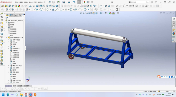
4. The Base: Ground Contact, Stability and Movement
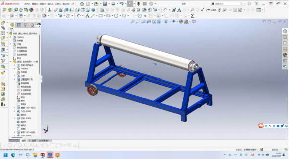
The base is the light-blue section highlighted in the 3D model. It carries every component installed above it and represents the most functionally detailed part of the product.
4.1 The Mixed Wheel-and-Leg Arrangement
The base has caster wheels on one side and fixed support legs on the opposite side.
| Base Element | Location | Função |
|---|---|---|
| Heavy-duty swivel casters | One side of the base | Provide the mobile ground-contact points |
| Fixed support legs | Opposite side of the base | Prevent the rack from rolling while it is parked |
| Front support leg | Front of the base | Provides additional stability during loading and unloading |
| Combined action | Wheels and fixed legs together | Keep the A-frame upright and balanced while stationary |
The rack therefore has a stable working position without requiring the wheels to be locked every time it is used.
4.2 Why a Mixed Arrangement Is Used
| Alternative Arrangement | Operational Consequence |
|---|---|
| Wheels at all four corners | The rack can roll or drift during loading unless separate locks are fitted |
| Fixed legs only | The rack cannot be repositioned without lifting equipment |
| Wheels on one side and fixed legs on the other | The rack remains stable when parked while retaining a towing capability |
| Effect during roll loading | Heavy rolls can be loaded without the rack moving across the floor |
| Effect during relocation | The rack can be moved using compatible towing equipment |
This arrangement reflects the way a fabric-roll rack is normally used. It stands in one position for extended periods and is loaded with heavy rolls, but it may still need to be moved when the production layout changes.
4.3 Caster-Wheel Construction
The workshop video examined the wheel assembly in detail. The presenter described it as a heavy-duty swivel caster with an iron core and nylon outer ring.
| Wheel Component | Recorded Construction | Purpose |
|---|---|---|
| Wheel core | Iron core | Carries the structural load and forms the wheel hub |
| Outer running ring | Nylon outer ring | Provides the contact surface against the workshop floor |
| Axle | Long axle connecting the wheel to the base bracket | Transfers the wheel load into the base |
| Axle-end retention | Cotter pin or slotted nut, as described | Mechanically secures the wheel on the axle |
| Swivel arrangement | Industrial swivel caster | Allows the wheel to change direction while the rack is towed |
The iron core and nylon outer ring form a practical combination: the core provides strength, while the nylon surface provides a resilient running interface that is less likely to damage a workshop floor.
4.4 The Axle-End Retention Detail
The axle-end fastener is a small feature, but it directly affects whether the wheel remains securely attached.
| Condition | Potential Consequence |
|---|---|
| Thread alone used as the only retention | Repeated industrial shock may gradually loosen the wheel |
| Cotter pin fitted | Provides a positive mechanical lock against axial movement |
| Slotted nut fitted | Prevents the nut from turning during service |
| Missing or damaged retainer | The wheel can move on the axle or separate from the bracket |
| Inspection requirement | The axle-end fastener should be checked during routine maintenance |
A strong wheel core is only useful if the wheel is positively retained on its axle.
5. Movement: Why Only Two Wheels Move
The presentation directly addressed the question that naturally follows from the wheel-and-leg arrangement: if the rack has wheels, how is it moved?
5.1 The Hollow Front Interface
At the front of the base is a hollow tubular fitting. The presenter identified this fitting as the reason only the two wheels are mobile.
| Base Element | Recorded Description | Função |
|---|---|---|
| Hollow front fitting | Tubular element at the front of the base | Provides the connection point for a towing accessory |
| Towing accessory | A separate accessory fitted to the front interface | Connects the rack to suitable towing equipment |
| Rear casters | Two mobile ground-contact points | Support the rack while it is towed |
| Front support position | Fixed or guided by the towing arrangement | Keeps the front of the rack aligned with the direction of travel |
| Resulting movement | The complete rack is repositioned as one unit | No manual pushing or lifting is required |
The video did not present the rack as a hand-push product. Instead, movement is designed around a connection to separate towing equipment.
5.2 The Mobility Concept
| Aspecto | Arrangement |
|---|---|
| Movement method | Connection to a towing device through the front fitting |
| Towing accessory | Supplied or selected as a separate interface component |
| Stability during movement | The two casters and towing connection form the mobile support arrangement |
| Direction changes | The swivel casters allow the rack to follow the towing path |
| Customer equipment | Ideally uses towing equipment already available in the plant |
| Positioning objective | Move heavy fabric rolls without manually pushing the complete rack |
5.3 Practical Requirements for the Customer
| Consideration | Effect on Selection and Operation |
|---|---|
| Towing-equipment availability | The plant must have a compatible device or procure the required accessory |
| Connection compatibility | The hollow interface and towing accessory must match |
| Floor condition | A smooth, level floor supports more reliable movement |
| Turning space | The rack length and wheel arrangement determine its turning behavior |
| Load stability | The rack must remain within the approved load rating while being moved |
| Accessory identification | The towing accessory should appear as a separate documented item where required |
Mobility was designed as an interface with the customer’s towing equipment rather than as a proprietary self-propelled system.

6. The A-Frame and Its Bolted Connection
The A-frame was discussed from two perspectives: how it appeared in earlier reference photographs and how it will be constructed in the CRACK.
6.1 The Earlier Welded Reference Product
In the photographs used to introduce the product, the A-frame was welded directly to the base.
| Reference Characteristic | Resultado |
|---|---|
| A-frame-to-base connection | Permanent welded joint |
| Shipping state | A-frame remains fully erected |
| Transported profile | Full product height |
| Space efficiency | Limited because the complete erected structure must be packaged |
| Assembly at destination | No reassembly required |
| Handling difficulty | More awkward to package, stack and load into transport equipment |
6.2 The CRACK’s Bolted Connection
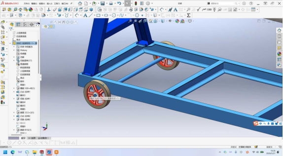
In the CRACK, the A-frame is bolted to the base, and the bolt holes have already been reserved in the model.
| CRACK Characteristic | Resultado |
|---|---|
| A-frame-to-base connection | Bolted joint |
| Bolt-hole preparation | Holes included in the base design |
| Shipping state | A-frame can be released and laid down with the base |
| Transported profile | Considerably lower and flatter than the erected product |
| Commercial purpose | Reduce container volume and export freight cost |
| Destination work | A-frame must be aligned, erected and bolted before use |
6.3 Why Export Economics Belong in the Product Structure
A bolted connection changes the physical product specifically to improve how it is transported.
| Direcionador de Custo | Effect of the Bolted Design |
|---|---|
| A-frame transport height | Reduced significantly when the frame is laid down |
| Container-volume utilization | More units can potentially be packed into the available space |
| Number of containers | Potentially reduced for the same order |
| Freight allocation per unit | Lower when more units fit into each container |
| Embalagem | A flatter package is generally easier to secure and handle |
| Customer assembly | A defined installation and bolting procedure becomes necessary |
The transport decision is therefore built into the structure rather than added later as a packaging workaround.
6.4 The Hinged Arrangement
The connection also includes a hinged structure, intended to make the transport arrangement more convenient.
| Hinged Feature | Explanation Given in the Presentation |
|---|---|
| Location | At the A-frame-to-base connection |
| Primary purpose | Transport convenience |
| Effect | The A-frame can be folded down relative to the base |
| Relationship to the bolt | The bolted joint allows the frame to be released for folding |
| Design precedent | The presenter stated that similar arrangements appear in materials he studied |
| Commercial objective | Reduce the transport volume of the assembled product |
6.5 Why the Existing Method Was Not Used
The presenter also discussed a common transport method in which several racks are nested inside one another.
| Transport Method | Assessment Given in the Presentation |
|---|---|
| Nesting multiple racks together | Unstable during transport |
| Nesting multiple racks together | Still occupies a considerable amount of space |
| Folding the A-frame down | Reduces the transported volume directly |
| Hinged and bolted design | Produces a lower, flatter package that can be secured normally |
The hinged and bolted A-frame is not merely an assembly convenience. It is a freight-cost decision built into the product structure.
6.6 Comparison of the Two Connection Strategies
| Aspecto | Welded Reference Product | Bolted and Hinged CRACK |
|---|---|---|
| Joint type | Permanent welded joint | Bolted joint with hinge provision |
| A-frame separation | Not possible | Possible |
| Transport profile | Full erected height | Low, flat package |
| Container utilization | Poorer | Better |
| Freight cost per unit | Mais Alto | Potentially lower |
| Assembly effort at destination | Nenhum | A-frame erection, alignment and bolting required |
| Structural continuity | Rigid and continuous | Depends on bolt and hinge integrity |
| Surface protection at joint | Primarily weld coating | Joint surfaces require defined treatment |
| Maintenance | No bolted-joint inspection | Bolts and hinge require periodic inspection |
A bolted design introduces responsibilities that a welded joint does not have. Before production release, the project should formally define the bolt grade, diameter, quantity, tightening method and torque, as well as the hinge-pin material, finish, retention method and inspection interval.
7. Bearing Housings: Supporting and Rotating the Roller
On both sides of the roller, the A-frame carries a bearing housing. The presenter made an important distinction between the housing and the bearing itself.
| Componente | English Term | Função |
|---|---|---|
| Bearing housing | Bearing housing | Supports the roller shaft and contains the bearing arrangement |
| Bearing | Bearing | The rolling element located inside the housing |
| Placement | One housing on each side of the roller | Provides symmetrical support at both ends |
| Primary purpose | Smooth roller rotation | Allows controlled loading and unloading of the fabric roll |
7.1 Why the Housing Is Important
| Design Consideration | Effect |
|---|---|
| Housing instead of a bare bearing | The bearing is correctly located and protected within the frame |
| Housing on both sides | The roller shaft is supported at both ends |
| Defined bearing axis | The roller remains aligned with the A-frame |
| Smooth rotation | A fabric roll can be placed and removed by rotating the drum |
| Reduced cloth damage | Less dragging reduces the risk of scuffing, folding or creasing |
| Maintenance access | The housing provides an access point for inspection and bearing replacement |
The bearing housing is the difference between a drum that rotates freely and one that resists movement. For fabric handling, that difference also affects the condition of the stored roll.
8. The Roller: A Hollow Drum Welded to Its Shaft
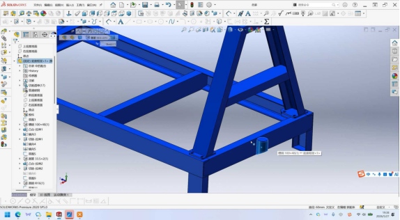
The roller is the component that directly supports the stored fabric, and the video used a cutaway model to show its internal construction.
8.1 Basic Construction
| Roller Feature | Recorded Description |
|---|---|
| Basic form | Hollow barrel or drum |
| End treatment | An end cap fitted to the drum end |
| Shaft connection | The shaft is welded to the drum assembly |
| Resulting assembly | One hollow-drum-and-shaft unit |
| Support method | Carried by bearing housings at both ends |
| Model presentation | Shown with a polished cutaway to expose the internal structure |
8.2 Reading the Cutaway
The presenter moved the section through the model and described the internal arrangement.
| Section Position | Visible or Described Feature |
|---|---|
| At the shaft end | The root of the shaft becomes visible |
| Moving inward from the shaft end | The hollow interior of the drum appears |
| Along the length of the drum | A continuous hollow barrel extends through the section |
| Overall interpretation | A tubular drum runs along the assembly with the shaft entering at one end |
| Section Observation | Engineering Implication |
|---|---|
| Continuous hollow interior | The roller is a tube rather than a solid billet, reducing material use and weight |
| Shaft entering at the end | The drum is supported through the shaft and bearing housings rather than along its full length |
| Welded shaft-to-drum joint | A critical structural connection requiring an approved welding procedure |
| Hollow geometry | Wall thickness and handling damage must be considered during fabrication |
8.3 Why a Hollow Drum
| Characteristic | Benefício |
|---|---|
| Reduced material consumption | Lower raw-material cost and lower unit weight |
| Reduced rotational inertia | The roller is easier to start and stop |
| Standard stock form | A hollow tube can be sourced and fabricated more readily than a solid billet |
| Structural adequacy | Depends on the specified wall thickness and material grade |
| Handling requirement | The tube must be protected against impact and deformation before fabrication |
The hollow drum is a practical weight and cost decision, but it makes the drum wall thickness and shaft-to-drum weld two of the roller’s most important engineering parameters.
9. Material Selection and Contamination Control
The presenter raised material selection specifically because of the product being stored.
| Consideration | Detail Given in the Presentation |
|---|---|
| Stored material | Cloth or fabric |
| Material sensitivity | Fabric may be susceptible to contamination |
| Material option | Some customers request 304 stainless steel |
| Application of the option | The roller, which is the surface in direct contact with the cloth |
| Reason for 304 | Its surface characteristics help reduce contamination risk to sensitive textiles |
| Default material | Standard steel unless 304 stainless steel is specified |
9.1 The Roller Is the Critical Contact Surface
| Superfície | Contact with Fabric | Contamination Relevance |
|---|---|---|
| Roller body | Direct contact with the fabric roll | Highest relevance |
| Roller end cap | May contact the edge of the roll | Moderate relevance |
| Bearing housing | No direct fabric contact | Low direct relevance, although its bore affects rotation |
| A-frame members | No direct fabric contact | Low relevance |
| Channel-steel frame | No direct fabric contact | Low relevance |
9.2 Comparing the Roller Material Options
| Aspecto | Standard Steel Roller | 304 Stainless Steel Roller |
|---|---|---|
| Purchase cost | Mais Baixo | Mais Alto |
| Surface-cleanliness control | Depends heavily on coating condition and handling | Better inherent cleanliness and corrosion resistance |
| Suitability for sensitive textiles | Suitable for less demanding applications | Preferred where contamination risk is important |
| Surface finish | Usually requires a protective coating | Can provide a clean, uncoated contact surface |
| Corrosion behavior | Dependent on coating integrity | Better inherent resistance |
| Maintenance | Coating condition must be inspected | Lower reliance on coating integrity at the contact surface |
| Primary selection driver | General use and budget | Cleanliness requirement and protection of fabric value |
The exact 304 scope should be defined before production. It may apply only to the roller surface or to the complete drum-and-shaft assembly, depending on the customer’s contamination standard.
9.3 Specification Points to Close
| Specification Item | Por Que É Importante |
|---|---|
| Roller material grade | Establishes the structural and contamination-control basis |
| Drum wall thickness | Governs deflection and resistance to handling damage |
| Scope of 304 material | Clarifies which parts of the assembly must be stainless steel |
| Contact-surface finish | Determines whether the roller can mark or contaminate the fabric |
| Carbon-steel coating specification | Must withstand repeated cloth contact without damaging the textile |
| Welding consumables and procedure | Critical for maintaining stainless-steel cleanliness and corrosion resistance |
For fabric handling, the roller material is part of the product-contact specification. It should not be treated as a finishing preference after the structure has been released.

10. The Lower Frame: Channel-Steel Sections
The lower structural framework uses channel-steel sections.
| Frame Member | Recorded Specification | Role |
|---|---|---|
| Section form | Channel steel | Forms the common structural frame |
| Section designation | Described as No. 10 channel | Size reference used in the presentation |
| Altura | 100 mm | Vertical dimension stated by the presenter |
| Largura | 100 mm | Width stated by the presenter |
| Wall thickness | Not stated | Required for structural and weight calculations |
| Material grade | Not stated | Required for load verification |
| Quantity | Not stated | Defines the complete frame configuration |
10.1 A Note on the Section Designation
The spoken description refers to a No. 10 channel with a height and width of 100 mm. Because standard channel designations and the dimensions given in the video may not correspond exactly, the released drawing should be checked before this section is used in a quotation or technical agreement.
| Point | Treatment |
|---|---|
| Section name stated in the video | No. 10 channel |
| Dimensions stated in the video | 100 mm high and 100 mm wide |
| Required verification | Actual height, flange width, web thickness and material grade |
| Possible issue | A standard channel designation may not normally produce the stated width combination |
| Commercial significance | Section properties affect weight, deflection, weld design and load capacity |
The familiar section name should be verified against the released drawing. Its actual dimensions—not the spoken description—must govern production.
10.2 Why Channel Sections Are Suitable
| Propriedade | Benefit in the CRACK |
|---|---|
| Bending stiffness | Resists deflection under fabric-roll loads |
| Open profile | Easy to weld, inspect and repair |
| Standard availability | Simplifies procurement and packing |
| Load distribution | Transfers roller reactions into the base and A-frame |
| Familiar fabrication | Reduces manufacturing complexity for the supplier |
11. Multi-Unit Row Configuration
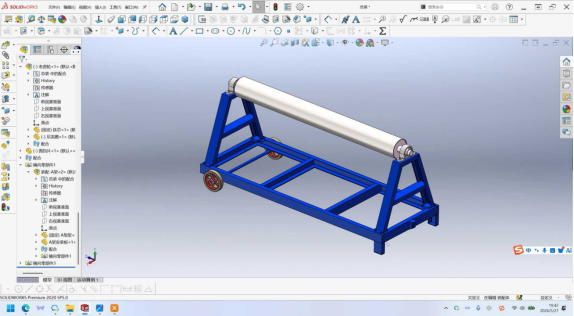
The 3D model shows a complete row consisting of multiple CRACK units.
| Configuration Aspect | Recorded Detail | Implication |
|---|---|---|
| Presentation view | A complete row of multiple units | The product is shown in a modular row arrangement |
| Unit structure | Each unit contains a base, A-frame and roller | The description applies to one repeated unit |
| Material stored | Multiple fabric rolls across the row | Supports a continuous roll-storage position |
| Roll access | Between the corresponding units | Influences loading and picking clearance |
| Row dimensions | Not stated | Requires a dedicated layout drawing |
| Unit connections | Not disclosed | Structural continuity between units must be confirmed |
| Towing arrangement for the row | Not disclosed | Must be defined before the row is offered as one movable assembly |
Several questions remain to be answered before a row configuration can be released as a single product arrangement.
| Open Design Question | Why It Must Be Resolved |
|---|---|
| Are adjacent units structurally connected? | Affects stability and handling of the complete row |
| Can the row be towed as one assembly? | Determines the required towing interface and method |
| Is the base continuous or discrete? | Changes the structural design and packing method |
| What is the required aisle width? | Controls forklift or trolley access between rolls |
| What is the maximum number of units per row? | Defines the product module |
| How are the units aligned during installation? | Required for repeatable roller positioning |
| Can the row be shipped in sections? | Determines container utilization and destination assembly |
12. Design Status and Items Requiring Engineering Closure
The presenter was clear that the 3D solid model represents a development stage rather than a final production release.
| Development Item | Status in the Presentation |
|---|---|
| 3D solid model | Completed and used to explain the product structure |
| Document control | The model is to be uploaded to the corresponding product-management document library |
| Future development | Further product changes are expected |
| Basic structure | The base, A-frame and roller arrangement is presented as the retained foundation |
| Application content | Usage, operating conditions and target scenarios are discussed separately |
| Production release | Dimensions, ratings and critical connection specifications still require formal closure |
12.1 Recommended Technical Release Checklist
| Open Item | Why It Must Be Closed | Priority |
|---|---|---|
| Overall dimensions and unit spacing | Required for layout, transport and installation | Alto |
| Roller length, diameter and wall thickness | Defines capacity and structural adequacy | Alto |
| Maximum roll weight and deflection limit | Determines bearing and drum requirements | Alto |
| Channel-section dimensions, thickness and grade | Confirms the lower frame’s load capacity | Alto |
| Bearing type and housing specification | Affects rotation, service life and maintenance | Alto |
| Bolt grade, quantity and tightening torque | Replaces the welded reference connection | Alto |
| Hinge-pin material, finish and retention method | Allows controlled folding and transport | Alto |
| Joint surface treatment | Protects the bolted and hinged connection | Alto |
| Coating specification | Must suit textile-industry and export conditions | Alto |
| Scope of the 304 stainless option | Determines which components require stainless steel | Médio |
| Caster load rating and floor-use limits | Govern safe movement and loaded stability | Médio |
| Towing-accessory specification | Confirms the movement interface | Médio |
| Multi-unit row connection detail | Required before offering a connected row | Médio |
| Packaging and container-loading plan | Verifies the export-cost objective | Médio |
| Installation and operating instructions | Supports correct customer assembly and use | Médio |
13. Lessons from the CRACK Product Structure
1. The Name Describes the Geometry
The fabric-roll A-frame and printing-and-dyeing-plant A-frame names identify both the stored material and the target industry. The A refers to an actual structural member rather than a decorative family name.
2. Three Assemblies Provide a Clear Structural Model
Base, A-frame and roller form a concise product architecture. This makes the design easier to explain, control, manufacture and maintain.
3. Mobility Should Match the Plant
Caster wheels on one side, fixed legs on the other and a towing interface at the front keep the rack stable when parked and allow it to be repositioned with compatible plant equipment.
4. Small Retention Features Govern Real Reliability
The cotter pin or slotted nut at the caster axle end prevents the wheel from working loose under repeated industrial shock. Small fasteners can determine whether a complete assembly remains reliable.
5. Export Economics Belong in the Structural Design
The bolted and hinged A-frame reduces the transport envelope. The alternative—nesting—was rejected because it remained both unstable and bulky.
6. The Contact Surface Is a Product Feature
Because fabric can be sensitive to contamination, 304 stainless steel may be specified for the roller. The material choice protects the customer’s product, not merely the rack.
7. Familiar Section Names Must Still Be Verified
A spoken reference to a No. 10 channel with stated dimensions is not enough to release a production drawing. The actual section properties must govern the design.
8. A Concept Model Is Not Yet a Production Release
The 3D model establishes the basic structure, but critical dimensions, ratings, connections, materials and packing requirements still need formal engineering approval.
14. Where the CRACK Structure Fits
| Application Area | How the Structure Supports It |
|---|---|
| Printing and dyeing plants | The product was developed around the material-handling needs of this industry |
| Fabric-roll storage in a production area | The repeated row configuration supports multiple rolls in one storage line |
| Contamination-sensitive textiles | The optional 304 stainless-steel roller provides a higher-contamination-control standard |
| Plants with repositionable storage positions | The towing interface and swivel casters permit controlled relocation |
| Export-oriented supply | The folded A-frame package reduces transport volume and freight cost |
| Loading of heavy fabric rolls | The bearing housings allow controlled rotation during loading |
| Space-constrained empty storage | The bolted and hinged structure allows the product to be packed in a flatter form |
Conclusão
The CRACK has a deliberately understandable structure. The presentation explained it through three principal assemblies.
The Base
The base supports everything above it and provides the ground interface. Heavy-duty swivel casters with an iron core, nylon outer ring, long axle and cotter pin or slotted nut are fitted on one side. Fixed support legs on the opposite side and at the front keep the A-frame balanced when the rack is parked.
A hollow tubular fitting at the front receives a separate towing accessory. This is how the rack moves: it is designed to be connected to suitable towing equipment rather than pushed manually.
The A-Frame
The upper support member forms the letter A that gives the product its name. Earlier reference photographs showed the A-frame welded directly to the base. In the CRACK, it is bolted, with the bolt holes already reserved in the model.
A hinged arrangement allows the frame to be folded down for transport. Nesting several racks inside one another was rejected because the presenter considered it unstable during transit and still too space-consuming. The objective is a flatter package that improves container utilization and reduces export freight cost.
The Roller
The roller is a hollow drum with an end cap, welded to a shaft and supported in bearing housings at both ends. A cutaway view showed the shaft root at one end and a continuous hollow barrel through the assembly.
Because fabric is susceptible to contamination, some customers can specify the roller in 304 stainless steel. This provides a more suitable contact surface for higher-value or contamination-sensitive textile products.
The Frame and Design Status
The lower framing uses channel steel, described in the presentation as No. 10 channel with a height and width of 100 mm. The exact section properties must be confirmed against the released drawing.
The completed 3D solid model is intended for the product-management document library, and further product changes are expected while the base, A-frame and roller architecture is retained. Usage, operating scenarios and working conditions are covered separately.
The CRACK earns its simplicity honestly: a stable base that can be towed, an A-shaped support that can be unbolted and folded for shipment, and a hollow roller that turns smoothly and can be made from stainless steel when the stored cloth demands it.
Tell us your fabric-roll diameter and weight, the number of rolls you store in one line, the floor and aisle conditions, and the towing equipment you already run. We will confirm the base configuration, roller material scope, bolted and hinged A-frame arrangement and packing plan against your released drawings before production. Send Your Fabric-Roll Specifications