CONFIGURATION GUIDE
Size an Erack Mold Rack from Mold Dimensions and Load
If you are comparing drawer sizes from 850 × 850 mm to 1350 × 1250 mm, start with the mold envelope, the number of storage levels, and the actual weight on each drawer—not with a nominal rack label.
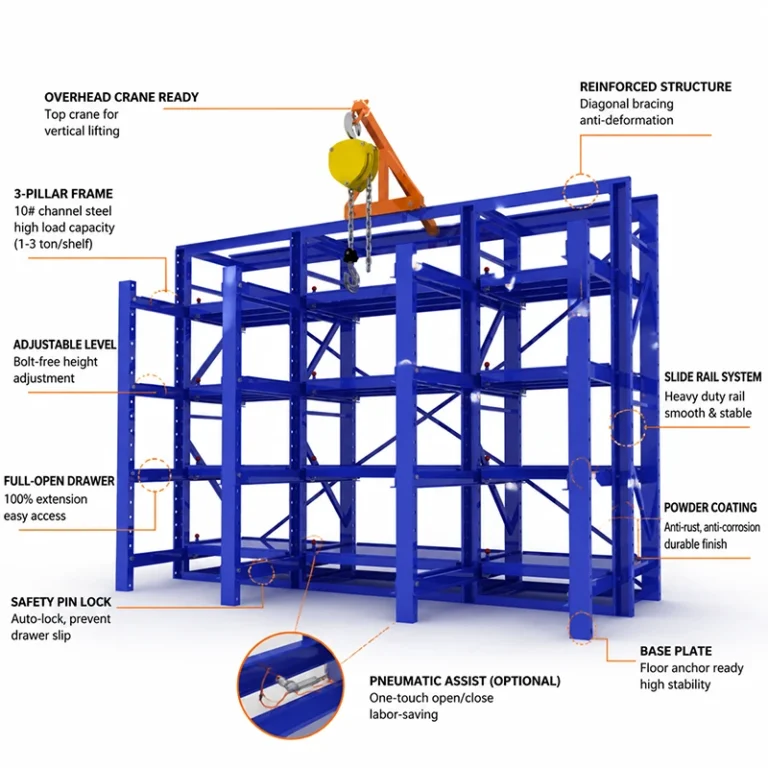
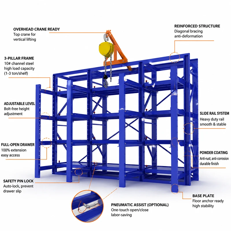
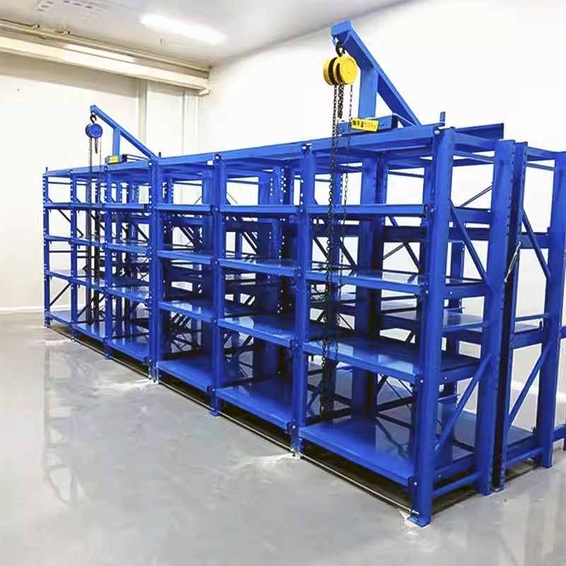
This Erack sizing guide is for engineers searching how to size a mold rack or mold drawer dimensions. Use the largest mold length, width, height, lifting clearance, and single-mold weight as the input set. The drawer size is a representative configuration dimension and must leave handling clearance around the mold; the number of levels is limited by clear height, crane travel, safe access, and the need to return one drawer before opening another. Erack uses full-extension drawers, steel guide rails with bearing support, safety locking features, and anchored uprights, but there is no single universal load table for every span, drawer size, floor, or installation. Treat the examples below as configuration starting points and submit the complete dimensions and loads for final engineering selection.
- Match drawer length and width to the largest mold footprint plus verified handling clearance.
- Choose 2–4 levels only after checking mold height, lifting headroom, access sequence, and anchoring conditions.
- Distribute the heaviest actual mold to the selected drawer; a 0.5–3 t input is not a blanket rating without an engineering confirmation.
- Select 100 × 42 × 4 mm 10# channel uprights or 90 × 50 × 2.5 mm C-section uprights from the confirmed load, span, height, and stability conditions.
Configuration Starting Points—Then Confirm the Boundary

850 × 850 mm drawer: compact mold footprint
Use this as a starting point when the largest mold footprint fits within 850 × 850 mm with a practical lifting and positioning margin. Do not force a mold to fit by ignoring protrusions, lifting points, or drawer edge clearance; confirm the actual envelope before ordering.

1050 × 1050 mm drawer: balanced general configuration
A representative mid-size option for molds that exceed the compact footprint but do not require the largest tray. Confirm mold length, width, height, center of gravity, drawer travel, and the clear vertical path for the overhead crane.

1250 × 1050 mm drawer: longer or wider mold envelope
Consider this configuration when one plan dimension or the required handling margin is greater than the mid-size drawer allows. The larger platform can change span and load effects, so do not transfer a smaller-drawer load assumption to this option.
1350 × 1250 mm drawer: largest representative footprint
Use this as a representative upper footprint in the requested range for large molds, subject to the final mold envelope, drawer structure, guide arrangement, floor anchoring, and crane clearance. It is not an automatic approval for any 3 t load.
How to Make the Engineering Decision
1. Match the drawer to the mold envelope
Record the largest mold length × width × height, including handles, fittings, lifting eyes, plates, and any overhang. Select a drawer that provides usable support and handling clearance rather than matching the mold to the nominal outside dimension. If the mold is close to an envelope limit, move to the next representative drawer size and request confirmation.
2. Set the number of levels from access, not storage count alone
Two levels may suit a low-clearance area or taller molds; three levels can balance density and access; four levels may work only when clear height, lifting travel, drawer spacing, and safe operator access are verified. Check the top-of-rack height and crane hook travel before treating 2–4 levels as available options.
3. Assign the actual single-layer load
For every drawer, list the mold's shipping or operating weight and any fixture or pallet weight. The requested 0.5–3 t range is an input range, not a universal promise. The source material identifies approximately 1,000–3,000 kg as a stated single-layer range for the product family, while the final allowed load depends on drawer size, span, support, load distribution, and installation; obtain the project-specific confirmation.
4. Choose the upright section from the complete load case
The 100 × 42 × 4 mm 10# channel section is the heavier starting section for demanding load, height, span, or stability conditions. The 90 × 50 × 2.5 mm C-section may be considered only when the confirmed project load case and structural review allow it. Section choice cannot be made from mold weight alone; include drawer extension, eccentric loading, overall height, bracing, anchoring, and floor condition.
5. Stop when the boundary is unknown
Do not approve a design when the mold weight is estimated, the center of gravity is unknown, the drawer dimensions are undersized, several full drawers may be opened together, the floor cannot accept anchors, or no project load confirmation is available. Erack is an anchored, crane-coordinated system—not a freestanding shelf for unverified overloads.
A Practical Sizing Workflow for an RFQ
-
Step 1 — Build the mold input sheet
Submit the largest and typical mold length, width, height, gross weight, center of gravity, lifting points, support surface, and whether a pallet or fixture stays on the drawer.
-
Step 2 — Select a representative drawer envelope
Compare the input with 850 × 850, 1050 × 1050, 1250 × 1050, and 1350 × 1250 mm starting dimensions. Record the required handling clearance and flag any mold that exceeds the largest representative footprint.
-
Step 3 — Select levels and clear height
Specify 2, 3, or 4 levels as a layout proposal, then check floor-to-ceiling height, crane hook travel, mold height, drawer spacing, front access, and the safe return-and-lock sequence.
-
Step 4 — Validate the upright and operation boundary
Compare the 10# channel and C-section options against the confirmed load, drawer span, extension condition, total height, bracing, anchor points, and floor construction. Request the project-specific structural confirmation before fabrication.
Mold Rack Sizing Questions Engineers Ask
How do I match a mold to an 850 × 850 mm or larger drawer?
Compare the complete mold footprint, including plates, fittings, lifting points, and any carrier, with the usable drawer support area. Add the handling clearance needed for safe placement and crane access. If the mold is close to the limit or has an irregular shape, step up to a larger representative size and submit the drawing for confirmation.
How many levels should I specify—2, 3, or 4?
Start with the required number of molds, then check mold height, level spacing, total rack height, crane hook travel, operator access, and the rule that the previous drawer must be returned and locked before another drawer is opened. More levels are not automatically suitable when clear height or lifting access is limited.
Can I assign any 0.5–3 t mold to a drawer?
No. The range describes the sizing input requested for this page, not an unconditional rating. Product material states a single-layer range of approximately 1,000–3,000 kg for the product family, but there is no universal load table covering every drawer size, span, load distribution, extension condition, and floor. A 0.5 t mold still needs a confirmed drawer and structure; a 3 t mold requires project-specific engineering confirmation.
How do I choose between the 10# channel and C-section?
Use the 100 × 42 × 4 mm 10# channel as the heavier starting option when the confirmed load case, rack height, drawer span, extension, eccentricity, or stability demand is more severe. The 90 × 50 × 2.5 mm C-section may be considered only after review of the complete project geometry and load case. Do not infer equivalence from nominal dimensions.
What is the overload or no-load-table stop rule?
Stop the selection when the actual mold weight, center of gravity, support condition, drawer envelope, floor anchoring, or permitted single-layer load is unknown. Also stop if the design assumes multiple full drawers open at once. Submit the missing data for exact selection instead of approving an unverified limit.
What should I send for exact selection?
Send the maximum and typical mold length, width, height, gross weight, center of gravity, lifting method, requested number of levels, available clear height, floor construction, crane capacity and travel, preferred drawer layout, and any pallet or fixture retained during storage. Use the inquiry form to request exact selection, and compare the related PDP-01, PDP-04, PDP-05, and BLOG-06 guidance where relevant.