
DERACK Acceptance Inspection: Dimensional Checks, a 2.3-Tonne Load Test and Plug-In Verification
Acceptance inspection of a hot-dip galvanized DERACK plug-in rack for 6-metre tube: frame construction, dimensions, 4.5 mm main beam, self-weight, 2.3 t static load test, forklift handling and plug-in verification.
Acceptance Inspection: Dimensional Checks, a 2.3-Tonne Load Test and Plug-In Verification
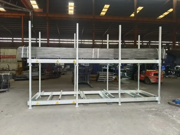
How a hot-dip galvanized DERACK plug-in rack for 6-metre tube material is verified: frame construction, galvanizing openings, dimensions, member thickness, self-weight, a static load test with approximately 2.3 t of workshop tube, forklift handling, and a plug-in test on every tube before shipment.
Acceptance Inspection: Dimensional Checks, a 2.3-Tonne Load Test and Plug-In Verification
A rack that looks correct on the factory floor has not yet been accepted.
Acceptance requires the characteristics that can be measured to have been measured, and the functional risks that cannot be confirmed by appearance alone to have been physically tested.
This review covers DERACK product 130013801, a plug-in rack used to store 6-metre-long tube material. The frame receives a hot-dip galvanized surface treatment.
The acceptance inspection covered six principal verification areas:
Visual construction and galvanizing features
Overall dimensions
Member thickness
Product self-weight
Structural and dynamic handling tests
Plug-in performance after galvanizing
Each check addresses a different potential failure mode. Correct dimensions do not prove adequate strength, and adequate static strength does not guarantee safe forklift handling or trouble-free assembly.
Acceptance is not a single inspection. It is a sequence of checks covering geometry, material, structural performance, handling and assembly.
1. Acceptance Review at a Glance
| Item | Recorded Detail | Significance |
|---|---|---|
| Product code | 130013801 | Product covered by the acceptance review |
| Product | DERACK | Plug-in rack for long tube material |
| Stored material | 6-metre-long tube | Defines the intended loading arrangement |
| Surface treatment | Hot-dip galvanizing | Applied to the internal and external steel surfaces |
| Frame configuration | Two main beams | Sufficient for the relatively narrow rack width |
| Upright configuration | Eight uprights, four on each side | Provides symmetrical vertical support |
| Galvanizing openings | Multiple openings throughout the frame | Permit zinc circulation and internal coverage |
| Empty-state stacking | Empty racks can be stacked | Reduces idle storage and transport volume |
| Measured rack length | Tape reading of 5 m | Must be reconciled with the drawing and measurement datum |
| Upright height | Measured during acceptance | Exact verbal value not stated |
| Rack width | Measured during acceptance | Exact verbal value not stated |
| Main-beam specification | 4.5 mm-thick rectangular tube | Nominal wall thickness |
| Measured main-beam thickness | 4.6 mm | Consistent with the stated nominal thickness, subject to drawing tolerances |
| Other thickness checks | Fork-channel member, uprights and another tubular member | Exact readings not stated in the transcript |
| Product self-weight | Measured during acceptance | Used as an indirect material-consistency check |
| Drawing weight | Not stated | Required as the reference for the self-weight comparison |
| Load-test material | 6-metre rectangular tube from workshop stock | Realistic load using available production material |
| Applied test load | Approximately 2.3 t | Presenter initially referred to two tonnes and then recorded the weighed value |
| Static load inspection | Check for weld opening and deformation | Confirms structural integrity under the applied load |
| Forklift handling test | Empty and loaded rack transfer | Verifies dynamic performance under the customer’s handling method |
| Post-load inspection | Rack inspected from around its perimeter | Detects deformation that may not be visible from one position |
| Plug-in test | Performed on every tube before shipment | Confirms that retained zinc does not obstruct column insertion |
| Non-conformance action | Obstructed components repaired in the factory | Prevents defective units from reaching the customer |
The source does not disclose the certified load rating, exact rack dimensions, drawing weight, galvanizing standard, coating thickness or permitted inspection tolerances. The observations in this article must be reconciled with the released drawing and acceptance record.
2. Why Acceptance Requires More Than a Visual Check
A completed rack can appear correct while still presenting a risk in service.
| Acceptance Check | Failure Mode It Detects |
|---|---|
| Construction review | Incorrect beam, upright or opening arrangement |
| Overall dimensions | Wrong geometry affecting installation and site layout |
| Wall-thickness measurement | Under-specified material reducing structural capacity |
| Self-weight measurement | Incorrect material quantity or stock substitution |
| Static load test | Excessive deformation, connection failure or weld opening |
| Forklift handling test | Failure under dynamic loading, impact or lifting |
| Full-perimeter inspection | Bowing, twisting or distortion visible from only one direction |
| Plug-in test | Assembly obstruction caused by retained zinc residue |
A rack may pass a visual inspection and still have insufficient beam capacity. It may also pass a static load test and still be unsafe to move with a forklift.
Complete acceptance tests the product at every point where it can fail: in material selection, in fabrication, under load, during handling and during customer-side assembly.
3. External Appearance and Frame Construction
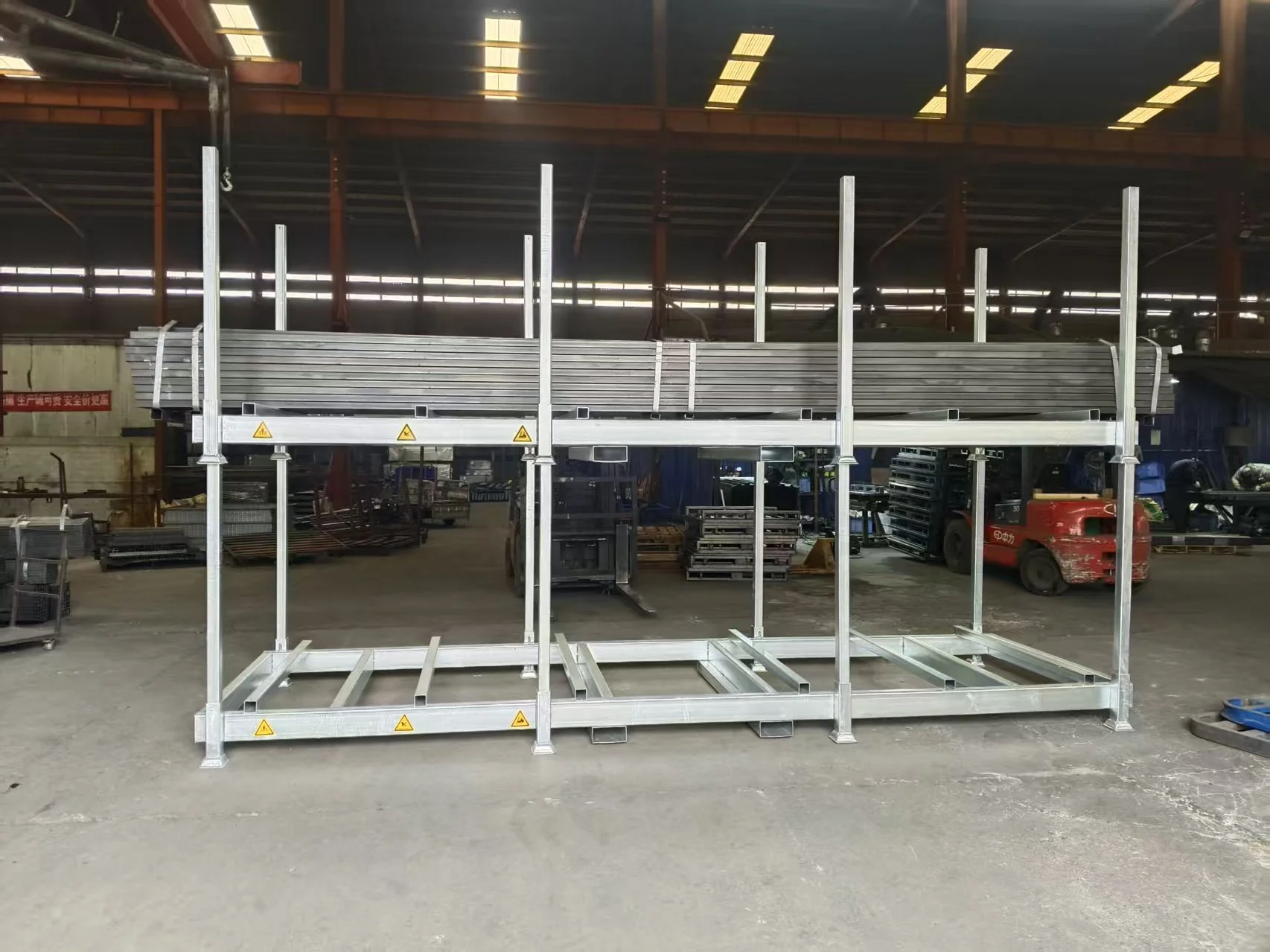
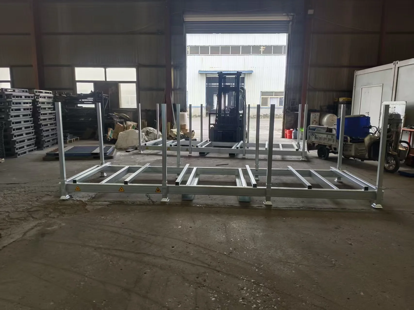
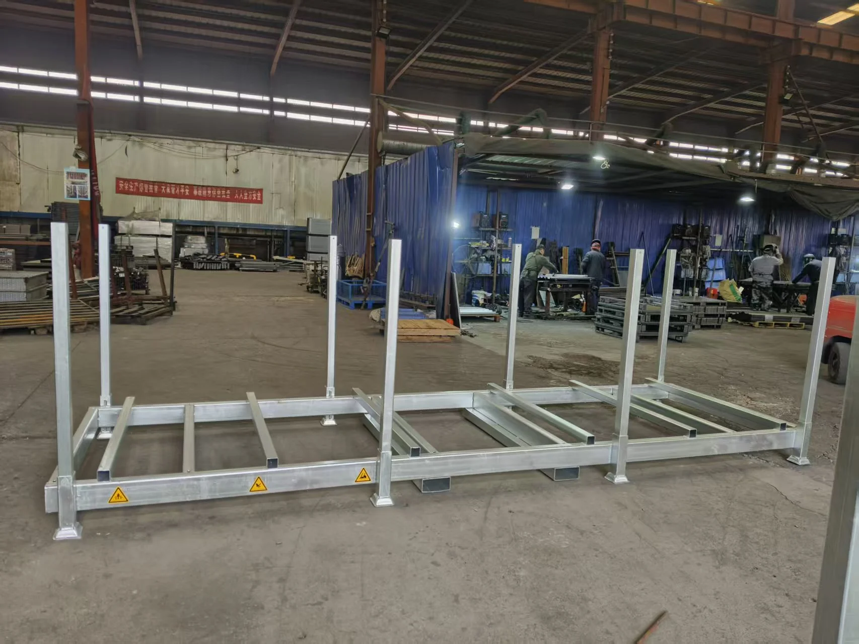
The completed DERACK uses a double-beam arrangement with eight uprights, with four uprights installed on each side.
| Structural Element | Recorded Configuration | Reason Given |
|---|---|---|
| Main beams | Two | The rack width is relatively small, so two beams were sufficient to meet the load requirement |
| Uprights | Eight | Distributed along the rack to support the main beams |
| Upright distribution | Four on each side | Provides balanced support along the full rack length |
| Overall construction | Plug-in | Allows assembly, disassembly and empty-state stacking |
| Surface finish | Hot-dip galvanized | Intended for outdoor or moisture-exposed service |
| Length | Tape measurement showing 5 m | Requires comparison with the released drawing and stored-tube arrangement |
3.1 Why Two Main Beams Were Sufficient
The presenter explained that the beam arrangement follows from the rack width.
| Design Condition | Structural Effect |
|---|---|
| Relatively narrow rack | Shorter unsupported span between the supporting uprights |
| Shorter span | Lower bending demand on each main beam |
| Reduced bending demand | Two main beams were considered sufficient for the application |
| Wider configuration | Would generally require a different or additional support arrangement |
| Principle | Beam count is determined by geometry and loading, not by a fixed product rule |
The frame should therefore not be described as permanently limited to two beams. It is the approved configuration for this particular rack width and loading arrangement.
3.2 The Galvanizing Openings
The frame contains a multi-hole structure because the product receives hot-dip galvanizing.
| Stage | Function of the Openings |
|---|---|
| During galvanizing | Allows molten zinc to enter the hollow tube sections |
| During galvanizing | Allows trapped air, zinc and processing liquid to escape |
| After galvanizing | Supports the formation of a complete internal zinc layer |
| During outdoor service | Provides a route for rainwater that enters the tube to drain away |
| Manufacturing benefit | Improves internal coating coverage |
| Service benefit | Reduces the retention of water inside the frame |
Hot-dip galvanizing protects the outside of the component because the entire fabricated steel assembly enters the zinc bath. Zinc can also coat the inside of a hollow section when the section has suitable ventilation and drainage openings.
The openings are not decorative perforations. They are part of the product’s internal corrosion-protection and drainage system.

4. Internal and External Corrosion Protection
The hot-dip galvanized treatment is presented as protecting the complete rack, whether or not rainwater enters the hollow sections.
| Condition | Consequence |
|---|---|
| External zinc coating only | Water entering a hollow section can reach unprotected internal steel |
| Internal and external zinc coverage | Both the outer frame and the internal cavity have a corrosion-resistant metallic barrier |
| Outdoor exposure | Rain, condensation and airborne moisture can enter or remain within the tube |
| Result of the opening arrangement | Internal water has an escape route, while the internal steel remains protected |
| Customer benefit | The hidden interior of the rack is not left as an unprotected corrosion point |
This is particularly important because internal corrosion can progress without being visible from the outside of the rack.
For a hollow-section rack, internal coverage is not an optional secondary requirement. It is part of the complete galvanizing system.

5. Empty-State Stacking: A Plug-In Product Benefits from Two States
The acceptance photographs included the empty rack in a stacked condition.
| Product State | Recorded Feature | Practical Result |
|---|---|---|
| Assembled and loaded | Uprights and main beams form the operating rack | Provides the required storage function |
| Assembled and empty | The product remains in its working configuration | Convenient when the rack must remain ready for use |
| Disassembled or nested for stacking | Plug-in components are removed or arranged for compact stacking | Reduces the footprint of idle racks |
| Shipping state | Components can be packed more compactly | Reduces the transport volume per unit |
| Customer-side assembly | Plug-in members are installed into the rack | Converts the delivered components into the operating product |
The plug-in structure therefore provides two separate benefits:
operational flexibility, because the rack can be assembled or dismantled;
logistical efficiency, because empty components can be stacked and shipped more compactly.
The same plug-in feature that makes the rack convenient to use also reduces the space it occupies when it is not in use.
6. Dimensional Verification
Dimensional inspection was divided into two principal groups:
the overall dimensions of the rack; and
the material thickness of its individual members.
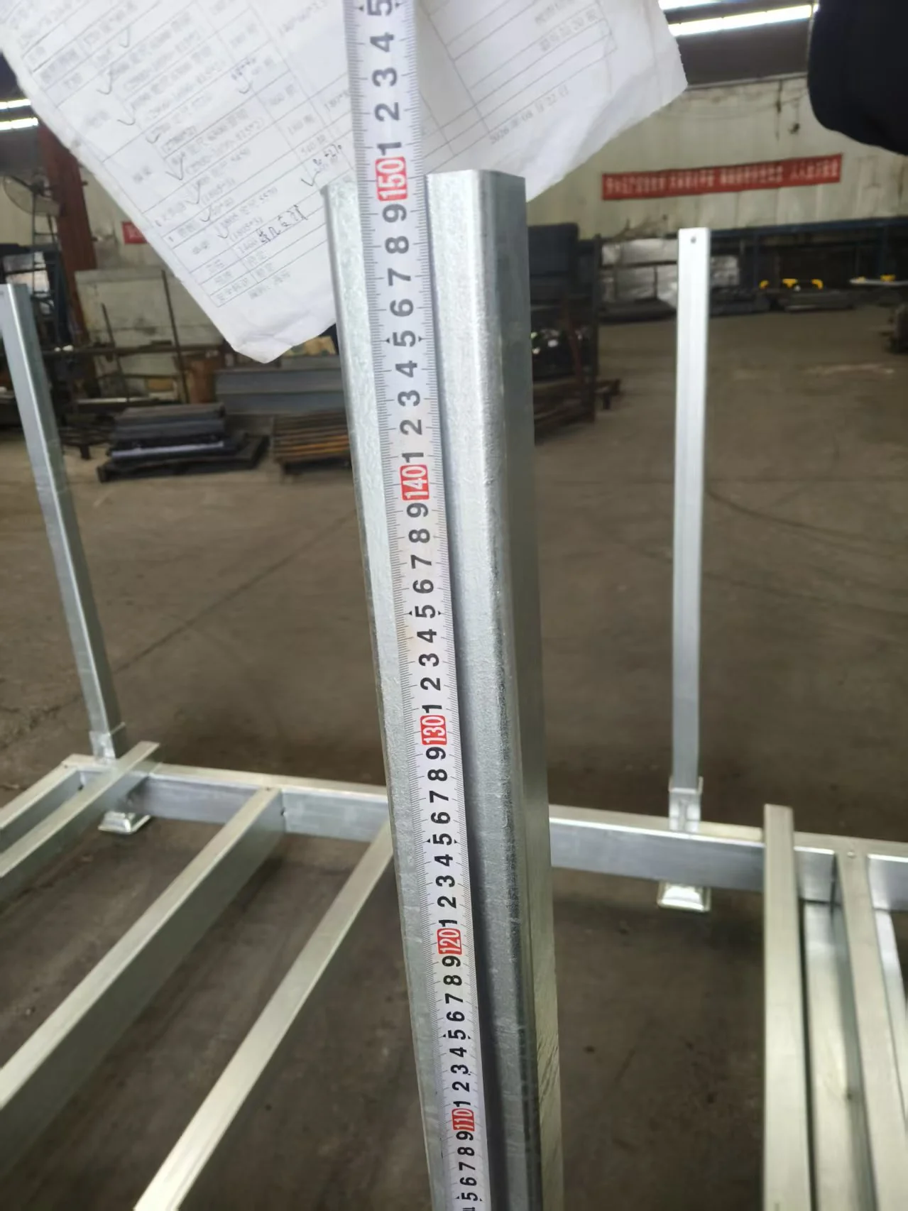
6.1 Overall Length, Height and Width
| Dimension | Verification Method | Recorded Result |
|---|---|---|
| Overall length | Tape measure placed along the rack | Tape reading of 5 m from one end to the other |
| Upright height | Tape measurement along an upright | Exact value not stated in the transcript |
| Overall width | Tape measurement across the rack | Exact value not stated in the transcript |
| General method | Direct measurement of the physical product | Confirms the delivered product rather than the drawing alone |
6.2 The 5 m Length Reading Requires a Defined Datum
The rack stores 6-metre tube, while the length measurement shown during acceptance produced a tape reading of 5 m.
This is not automatically a contradiction. The rack may store tubes with an overhang, or the measurement may cover only the frame between defined reference points.
| Point Requiring Confirmation | Why It Matters |
|---|---|
| Measurement reference points | Defines exactly what the 5 m reading represents |
| Overall frame length | Determines whether the reading covers the complete rack |
| Tube support and overhang arrangement | Explains how 6-metre material is supported |
| Drawing dimension | Provides the authoritative comparison value |
| Installation clearance | Confirms compatibility with the customer’s storage position |
| Acceptance-record wording | Prevents an ambiguous measurement from being published or installed incorrectly |
Every dimensional inspection record must identify the measurement points. A numerical length without a datum cannot be reconciled reliably with an engineering drawing.
6.3 Height and Width
| Inspection Item | Why It Matters |
|---|---|
| Upright height | Establishes the complete storage envelope and loading clearance |
| Rack width | Determines aisle space, forklift access and operating compatibility |
| Consistency between units | Confirms that multiple racks can be installed as a uniform storage line |
| Relation to stored material | Ensures the tube is supported and accessible as intended |
| Relation to handling equipment | Confirms the customer’s forklift and lifting arrangement can operate correctly |
Although the exact readings were not spoken during the presentation, the photographs should be retained with the acceptance sheet so that the measured values can be recovered and recorded.

7. Material Thickness Verification
The inspection also checked the wall thickness of the principal structural members.
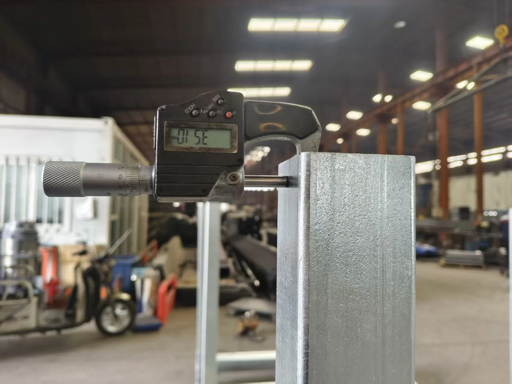
7.1 Main-Beam Measurement
The main beam was identified as a 4.5 mm-thick rectangular tube. The physical measurement returned 4.6 mm.
| Member | Nominal Specification | Measured Value | Acceptance Interpretation |
|---|---|---|---|
| Main beam | 4.5 mm-thick rectangular tube | 4.6 mm | Consistent with the stated nominal value and slightly above it |
| Structural relevance | Principal bending member | Verified on the physical product | Wall thickness directly affects stiffness and load capacity |
| Final acceptance basis | Drawing tolerance and applicable material standard | — | The measured value must satisfy the released requirements |
The 0.1 mm difference should be recorded exactly rather than normalized to 4.5 mm.
7.2 Other Thickness Checks
The acceptance images also showed measurements of the fork-channel member, the uprights and another tubular member.
| Measured Component | Verification Purpose | Clarification Required |
|---|---|---|
| Fork-channel member | Confirms the wall thickness of the member used for forklift engagement | Exact reading not stated |
| Upright | Confirms that the vertical structural members comply with the drawing | Exact reading not stated |
| Additional tubular member | Confirms the thickness of another frame component | Terminology was unclear in the recording |
| Main beam | 4.6 mm measured against a 4.5 mm specification | Stated clearly |
The additional member names and readings should be taken from the inspection sheet and released drawing. The transcript should not be used to assign a definite structural role where the original wording is ambiguous.
Where an inspection recording is unclear, the ambiguity should be resolved from the drawing rather than hidden behind a confident but unsupported description.

8. Self-Weight as an Indirect Material Check
The total self-weight of the completed rack was measured during acceptance.
8.1 The Logic of the Check
| Material Condition | Expected Effect on Total Weight |
|---|---|
| All members are manufactured to the drawing specification | Actual weight should be close to the calculated drawing weight, or slightly above it |
| Incorrect or insufficient material is used | The actual weight is likely to diverge from the drawing reference |
| A complete assembled product is weighed | The result reflects the aggregate effect of the finished bill of materials |
| Weight is compared with the approved drawing | A material discrepancy can be identified before shipment |
The presenter described total weight as an indirect verification of material usage. It does not directly identify which component is wrong, but it provides a simple aggregate check across the finished assembly.
8.2 Why It Complements the Dimensional Checks
| Inspection Method | What It Detects |
|---|---|
| Overall dimensional measurement | Incorrect frame geometry |
| Local wall-thickness measurement | Under-thickness steel at the measured location |
| Material-grade inspection | Incorrect grade or certification |
| Whole-product weight | Aggregate differences in material quantity or stock specification |
| Combined inspection | Much stronger confidence in material conformity |
8.3 The Record Required for a Defensible Comparison
| Acceptance Record Element | Purpose |
|---|---|
| Actual measured product weight | Establishes the delivered value |
| Calculated drawing weight | Provides the comparison reference |
| Permitted deviation | Determines whether the result is acceptable |
| Component weights or material quantities | Allows a discrepancy to be localized |
| Weighing equipment identification | Establishes the source of the measurement |
| Calibration status | Makes the recorded value traceable |
Self-weight is a useful early-warning check, but it is not a substitute for material certificates, section inspection or the drawing-to-product comparison.
9. Static Load Test with Real Workshop Material
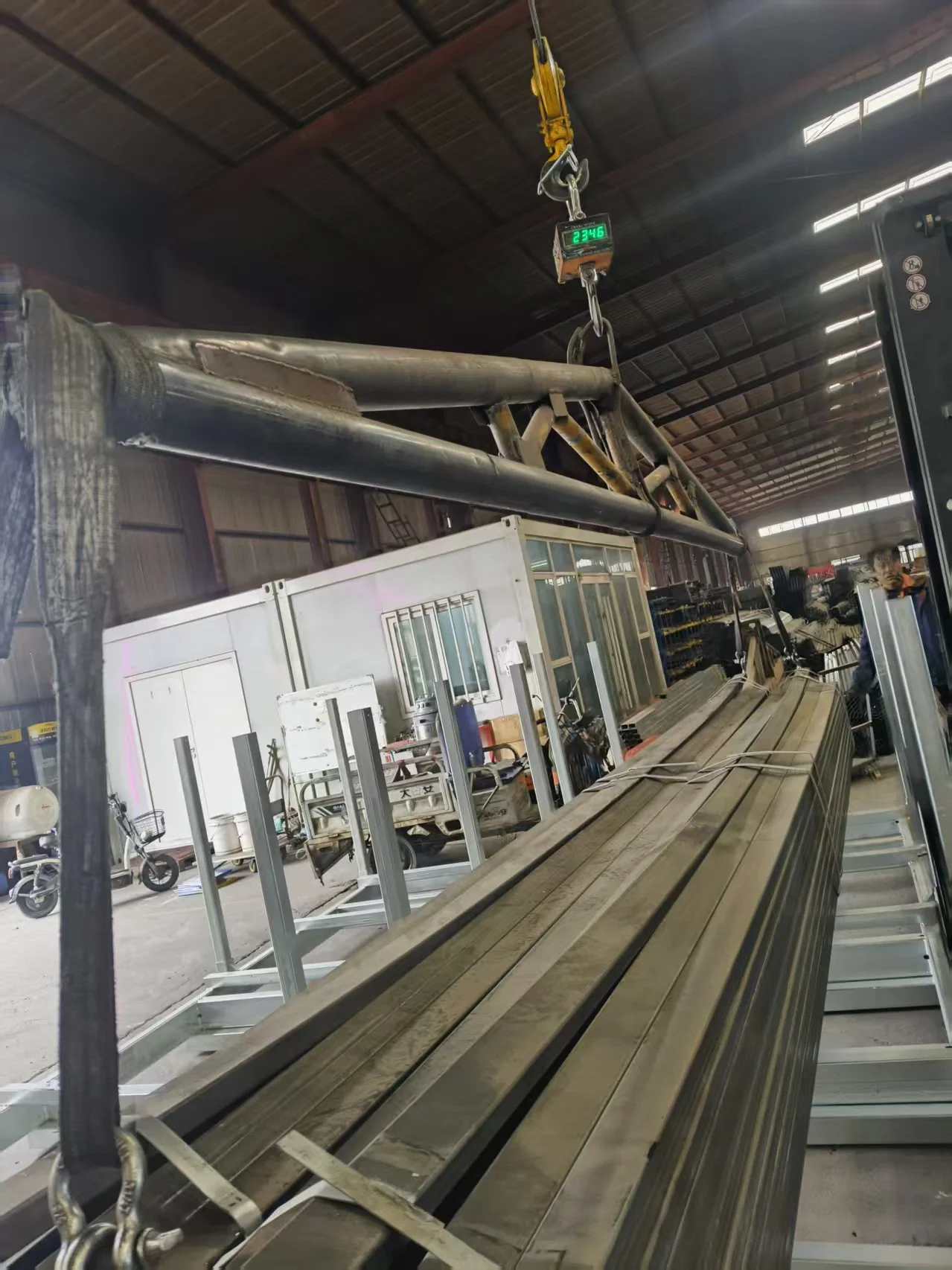
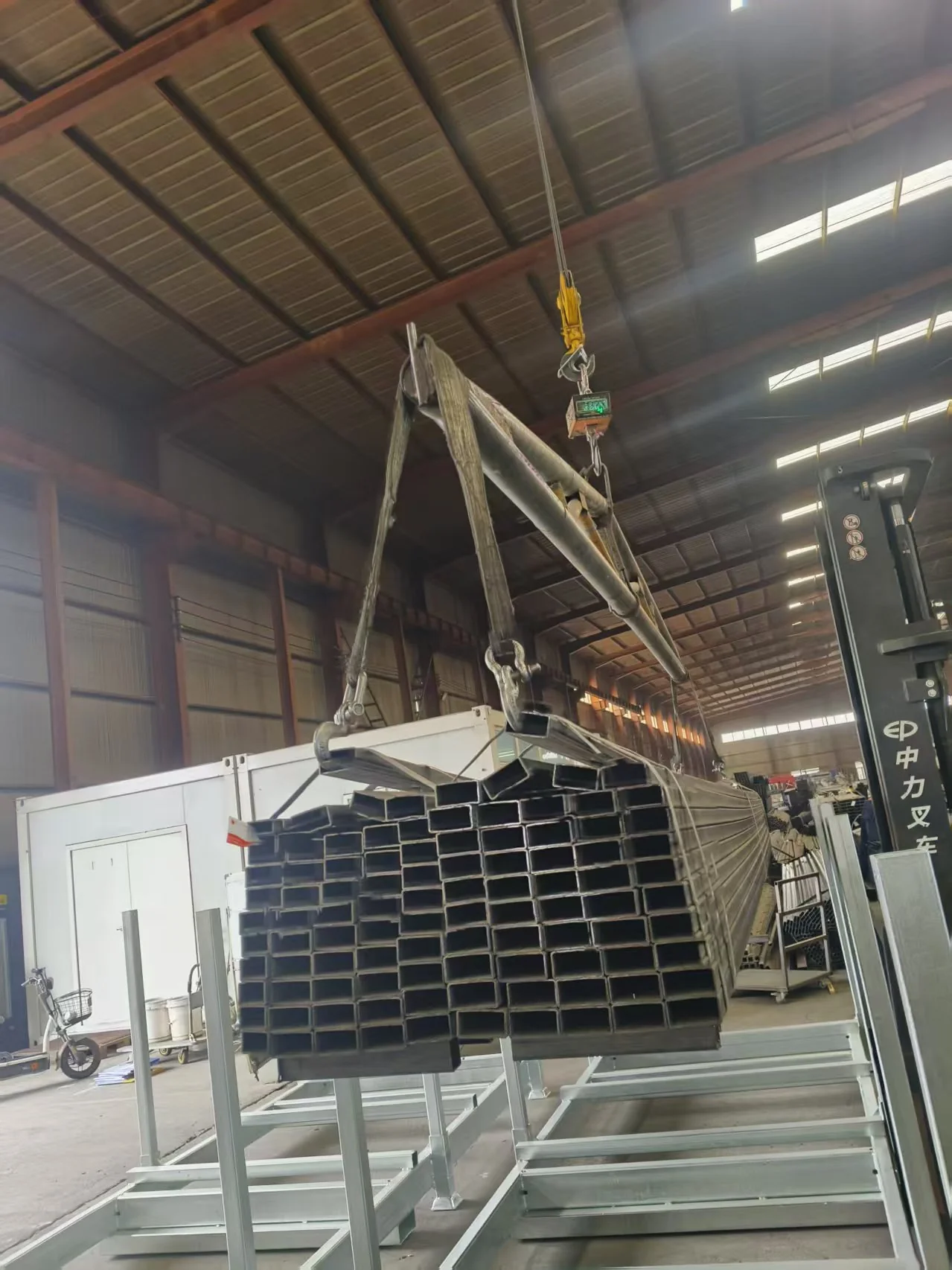
The central structural verification used tube material already available in the workshop.
9.1 The Test Load
| Test-Load Element | Recorded Detail |
|---|---|
| Test material | 6-metre-long rectangular tube |
| Source | Workshop raw-material stock |
| Initial verbal description | Two tonnes |
| Weighed value | Approximately 2.3 t |
| Load placement | Tube placed on the rack in its intended storage position |
| Acceptance purpose | Reproduce a realistic tube-storage load |
The applied load should be recorded as approximately 2.3 tonnes, because the presenter explicitly referred to the weighed result after initially describing the material as two tonnes.
9.2 What the Load Test Examines
| Inspection Criterion | Potential Failure Detected |
|---|---|
| Weld opening | Separation or cracking of a welded connection under load |
| Beam deformation | Excessive bending of the main-beam assembly |
| Upright deformation | Distortion of the vertical supports |
| Frame twist | Uneven loading or insufficient lateral stability |
| Local damage at the supports | Concentrated stress or connection failure |
| Post-test geometry | Whether the rack retains its intended form |
9.3 Load-Test Sequence
| Step | Action | Purpose |
|---|---|---|
| 1 | Select 6-metre rectangular tube from workshop stock | Provides a realistic test load |
| 2 | Weigh the test material | Establishes the applied load at approximately 2.3 t |
| 3 | Place the material on the rack | Applies the load in the intended storage arrangement |
| 4 | Inspect the welded connections | Check for weld opening |
| 5 | Inspect the main beams and uprights | Check for deformation |
| 6 | Walk around the loaded rack | Repeat the inspection from multiple directions |
| 7 | Record the result | Creates objective acceptance evidence |
9.4 Why the Full-Perimeter Inspection Matters
| Potential Distortion | Best Viewing Direction |
|---|---|
| Bowing in one vertical plane | Opposite side or end of the rack |
| Twist along the rack length | Both ends and both sides |
| Local bending beneath a load point | Low or oblique viewing angle |
| Settling at one support | Side elevation |
| Connection damage hidden behind a member | Direct access to the joint |
A single front-facing inspection can miss a rack that is bent or twisted away from the inspector.
The walk-around is not a ceremonial step. It is the most effective way to detect deformation that exists in a plane the inspector cannot see from one position.

10. Forklift Handling Test: Dynamic Strength Verification
In addition to the static load test, the product was handled with a forklift.
| Test Aspect | Recorded Purpose |
|---|---|
| Forklift transfer | Reproduce the customer’s actual method of moving the rack |
| Empty-rack handling | Verify movement before the rack is loaded |
| Loaded-rack handling | Verify the frame while carrying stored tube material |
| Dynamic loading | Check strength under movement, lifting and positioning forces |
| Video evidence | Preserve the behaviour of the product during handling |
| Acceptance outcome | Determine whether additional damage or distortion occurs |
10.1 Why Static and Dynamic Tests Are Different
| Comparison Factor | Static Load Test | Forklift Handling Test |
|---|---|---|
| Load application | Gradual and sustained | Concentrated and intermittent |
| Main effect | Bending, deflection and sustained structural stress | Shock, local stress, lifting and positioning loads |
| Typical failure mode | Weld opening or excessive member deformation | Connection damage, local buckling or frame instability |
| Operating relevance | Confirms capacity under the stored load | Confirms safe handling in the customer’s workflow |
A rack can support a static load and still show weakness when lifted, moved or set down.
Passing the static test does not automatically prove dynamic handling capacity. The forklift test verifies the rack under the movement method the customer will actually use.
11. The Mandatory Plug-In Test
The final acceptance check addresses a risk created specifically by hot-dip galvanizing.
11.1 Why Zinc Residue Can Obstruct Assembly
During galvanizing, zinc enters the hollow steel sections. Some zinc and process residue can remain inside after the component is removed and cooled.
| Condition | Possible Effect |
|---|---|
| Zinc remains in a liquid or semi-solid state during handling | It can collect at the end of the tube or inside a socket |
| Zinc solidifies after cooling | An internal obstruction is created |
| Plug-in member is inserted into the affected tube | Insertion becomes difficult or intermittent |
| Severe interference | The component may not reach the required seated position |
| Uncorrected condition | The customer may face installation delay, forced insertion or incomplete engagement |
11.2 The Factory Test
| Test Requirement | Recorded Arrangement |
|---|---|
| Frequency | Every tube is tested before shipment |
| Test action | The corresponding plug-in member is inserted and withdrawn |
| Purpose | Confirm that insertion and withdrawal are smooth |
| Failure action | Obstructed components are repaired inside the factory |
| Shipping rule | A unit that binds is not released in its obstructed condition |
| Verification value | Directly tests the assembly action the customer will perform |
11.3 Why Other Checks Cannot Replace It
| Inspection Method | Limitation |
|---|---|
| Visual inspection of the tube opening | Residue may be located deeper inside the section |
| Wall-thickness measurement | Confirms steel thickness, not internal clearance |
| Coating inspection | Confirms zinc coverage, not the absence of retained zinc |
| Weight measurement | May indicate a difference but cannot locate it |
| Plug-in test | Directly reproduces the customer’s assembly movement |
A known process risk requires a functional test. For a galvanized plug-in rack, exercising every tube is more reliable than looking into the tube and assuming the interior is clear.

12. Consolidated Acceptance Checklist
| No. | Acceptance Step | Method | Acceptance Requirement | Basis |
|---|---|---|---|---|
| 1 | Confirm frame configuration | Visual inspection against the released drawing | Two main beams and eight uprights, four per side | Stated in the source |
| 2 | Confirm galvanizing openings | Visual inspection | Openings present and unobstructed | Stated in the source |
| 3 | Confirm internal and external coating | Process and visual review | Both internal and external surfaces protected | Stated in the source |
| 4 | Measure overall length | Tape measurement with defined reference points | Matches the released drawing | 5 m reading shown |
| 5 | Measure upright height | Tape measurement | Matches the drawing | Exact value not stated |
| 6 | Measure overall width | Tape measurement | Matches the drawing | Exact value not stated |
| 7 | Measure main-beam thickness | Thickness measurement | Nominal 4.5 mm; measured 4.6 mm | Stated in the source |
| 8 | Measure fork-channel member | Thickness measurement | Matches the drawing | Exact reading not stated |
| 9 | Measure upright thickness | Thickness measurement | Matches the drawing | Exact reading not stated |
| 10 | Measure additional tubular member | Thickness measurement | Matches the drawing | Terminology and reading unclear |
| 11 | Measure total self-weight | Weighing | Reconciles with the drawing weight within the approved range | Stated in the source |
| 12 | Weigh the load-test material | Weighing | Approximately 2.3 t applied | Stated in the source |
| 13 | Load the rack | Static load test | Load maintained in the intended position | Stated in the source |
| 14 | Inspect welded connections | Visual inspection | No unacceptable weld opening | Inspection purpose stated |
| 15 | Inspect frame members | Visual inspection | No unacceptable deformation | Inspection purpose stated |
| 16 | Walk around the loaded rack | Full-perimeter inspection | No distortion from any direction | Stated in the source |
| 17 | Move the empty rack with a forklift | Dynamic handling test | No structural damage or instability | Stated in the source |
| 18 | Move the loaded rack with a forklift | Dynamic handling test | No structural damage or instability | Stated in the source |
| 19 | Test every plug-in tube | Functional insertion and withdrawal test | Smooth engagement on every tube | Stated in the source |
| 20 | Correct any obstruction | Factory repair and repeat test | Obstruction removed before shipment | Stated in the source |
| 21 | Confirm empty-state stacking | Visual inspection and photographs | Correct stacking arrangement | Stated in the source |
Opening diameters, dimensional tolerances, the drawing weight, certified load rating, galvanizing standard and formal pass/fail criteria were not disclosed and must come from the released project documents.

13. Lessons from the DERACK Acceptance Review
1. Acceptance Is a Sequence, Not a Single Event
Dimensions, thickness, weight, static load, dynamic handling and assembly each test a different failure mode. None can substitute for the others.
2. Weight Is a Useful Indicator of Material Consistency
If every member is manufactured to the drawing specification, the finished weight should be close to the calculated value. A significant deviation is an early warning that the material or fabrication process requires review.
3. Internal Galvanizing Is Part of the Delivered Protection
The openings allow zinc to reach the inside of the hollow sections. This protects the rack even if rainwater enters and provides a path for trapped water to escape.
4. A Static Load Test Does Not Replace Forklift Testing
Static capacity and dynamic handling are different requirements. The forklift test reproduces the actual movement method used by the customer.
5. Inspect the Rack from Every Direction
Walking around the loaded rack can reveal bowing or twisting that cannot be identified from the front alone.
6. Process Residue Must Be Tested Functionally
Retained zinc inside a hollow section can only be confirmed by exercising the actual plug-in movement. A visual inspection of the tube mouth is insufficient.
7. Correct Defects Before Shipment
An obstructed tube found at the factory can be repaired and retested. The same defect discovered at the customer’s site becomes an installation delay.
8. Plug-In Construction Creates a Logistics Benefit
The feature that allows the rack to be assembled and disassembled also allows empty racks to be stacked compactly, reducing idle floor space and transport volume.
14. Conclusion
The acceptance review of DERACK product 130013801 demonstrates a complete inspection sequence covering both physical characteristics and actual product performance.
Construction and Galvanizing
The rack uses a double-beam arrangement with eight uprights, four on each side. Because the rack width is relatively small, two main beams were considered sufficient for the load requirement.
The frame contains multiple galvanizing openings so that zinc can reach the internal tube surfaces. The result is protection on both the inside and outside of the rack, including when rainwater enters a hollow section.
Dimensional and Thickness Checks
Overall length, height and width were measured directly on the physical rack. The length tape showed a reading of 5 m, which must be reconciled with the drawing’s measurement datum and the arrangement used to support 6-metre tube.
Member thicknesses were also checked. The main beam was specified as a 4.5 mm rectangular tube, and the measured wall thickness was 4.6 mm.
Self-Weight Verification
The total product weight was measured as an indirect check on material usage. When all components are manufactured to the drawing specification, the finished weight should be close to the drawing weight or slightly above it.
Static Load Test
The rack was loaded with 6-metre rectangular tube weighing approximately 2.3 tonnes. The inspection focused on weld opening, member deformation and the general condition of the loaded frame. A second inspection was performed after walking around the rack, allowing deformation to be checked from multiple directions.
Forklift Handling Test
The empty and loaded racks were transferred with a forklift to verify dynamic strength under the customer’s actual handling method. This complements the static test by introducing concentrated and intermittent handling forces.
Plug-In Test
Because hot-dip galvanizing can leave residue inside the hollow sections, every tube was plug-in tested before shipment. Any component that inserted poorly would be repaired inside the factory and retested rather than released in an obstructed condition.
A product is accepted when every practical route to failure has been checked: geometry, material thickness, total weight, static capacity, dynamic handling and the actual assembly movement.
Send the stored tube dimensions, the required load, the rack length and the planned handling method. Steel Pallet will confirm the DERACK configuration and the acceptance checks to be recorded before shipment. Talk to the Steel Pallet engineering team