
Derack Hot-Dip Galvanized Tube Rack: 8 t Static Load, Drainage Holes and a One-Degree Pre-Tilt
Technical case on an outdoor Derack plug-in tube rack: 8 t static base load, two 2 t forklift-handled levels, a third channel beam, hot-dip galvanizing with drainage openings, post-galvanizing cleaning, plug-in flexibility testing and a one-degree column pre-tilt.
Derack Hot-Dip Galvanized Tube Rack: 8 t Static Load, Drainage Holes and a One-Degree Pre-Tilt
An outdoor tube-storage application in which the bottom level carries 8 t as a permanent static load while two upper levels are forklift-handled at 2 t each. A third channel beam, purpose-made galvanizing and drainage openings, post-galvanizing internal cleaning, a plug-in flexibility test and a one-degree inward column pre-tilt all came out of the same set of site conditions.

Derack Hot-Dip Galvanized Tube Rack: 8 t Static Load, Drainage Holes and a One-Degree Pre-Tilt
Storage racks are usually specified around what they will hold. Some applications, however, are determined by where the material will live and how the rack must be handled after it is installed.
This Derack application combines several demanding conditions:
the stored tube will remain outdoors and requires long-term corrosion protection;
the bottom storage level must carry an 8 metric ton static load;
the two upper storage levels must withstand forklift lifting operations;
the rack is approximately 5 m long and is intended to store approximately 6 m tube;
and, after unloading, the rack must be dismantled into a compact form that reduces transport and customer storage space.
These requirements resulted in a product that was more than a standard rack with a galvanized finish. The design required a third channel beam, functional galvanizing and drainage openings, post-galvanizing cleaning, a plug-in flexibility test, a deliberate one-degree column pre-tilt, and a packing arrangement based on the actual shipment.
A rack that stores 8 tons outdoors but must also be drained, emptied, shipped, re-erected and stacked is a different engineering problem from a rack that simply holds material in place.
1. Case Snapshot
| Item | Recorded Specification | Notes |
|---|---|---|
| Product | Derack plug-in tube rack | Modular construction using plug-in columns, sockets and beams |
| Application | Storage of long tube material | A common Derack product application |
| Recorded rack length | Approximately 5 m | The reviewed layout appears shorter than the stored material |
| Intended stored length | Approximately 6 m | Tube projection and final layout should be checked against the approved drawing |
| Recorded rack width | 1,490 mm | The width condition used for the beam arrangement |
| Storage environment | Outdoors | The driving condition behind the corrosion-protection requirement |
| Surface treatment | Hot-dip galvanizing | Selected for resistance to rain and outdoor weathering |
| Recorded zinc-layer requirement | At least 40 microns | Presented in the case review as supporting approximately 10 years of protection in the intended environment |
| Bottom storage level | 8 t static load | Storage function only; not intended for forklift handling |
| Upper storage levels | Two levels, each with a 2 t load requirement | Forklift-handled levels subject to dynamic loading |
| Main structural change | A third channel beam added at the middle | Added to the original two-beam arrangement |
| Production location | Hebei factory | Production, inspection and functional testing were completed there |
| Delivery status | Delivered at the time of the review | The video includes completed-product inspection and testing |
| Shipment arrangement | Small batch shipped by road to the port and then containerized | The review describes the quantity as nine units/sets |
These are the figures recorded in this application review. They describe the reviewed project and are not standard Derack catalogue specifications.

2. Why the Application Changed the Product
The final Derack solution was not a standard configuration with a different finish. Several separate aspects of the customer’s requirements shaped the design.
2.1 The Outdoor Storage Environment
The stored tube would remain outside the building. The rack would therefore be exposed to rain, moisture and weather-related corrosion.
| Customer Condition | Effect on the Product |
|---|---|
| Outdoor storage | Continuous exposure to rain and atmospheric conditions |
| Requirement for effective rain resistance | The corrosion-protection system must cover the external steel and the internal surfaces of hollow sections |
| Long-term storage application | Coating specification and tube-end design must be considered together |
| Empty tube ends | Closed sections require controlled openings for galvanizing and drainage |
This was the reason hot-dip galvanizing was recommended rather than a painted or powder-coated finish.
2.2 An Unusual Combination of Static and Dynamic Loads
The load arrangement is unusual and is worth reading carefully because it determines the beam design.
| Storage Level | Recorded Load | Handling Method | Main Structural Requirement |
|---|---|---|---|
| Bottom level | 8 t | Permanent static storage; no forklift handling | Static strength and controlled long-term deformation |
| Upper level 1 | 2 t | Forklift insertion, lifting, transportation and placement | Static capacity plus dynamic and repeated handling effects |
| Upper level 2 | 2 t | Forklift insertion, lifting, transportation and placement | Static capacity plus dynamic and repeated handling effects |
At first glance, the heaviest level appears to have the simplest operating requirement. In practice, however, an 8 t load cannot realistically be handled by a conventional forklift.
The bottom level was therefore treated as a permanent storage position. It was designed for the greater static load, but it was not expected to be repeatedly lifted.
The upper levels carried less material, but they were actually handled by a forklift. Fork insertion, lifting, transportation and setting down introduce additional effects that are not represented by a static load alone, including:
localized fork loading;
impact and shock during insertion;
repeated load cycling;
dynamic deflection;
and fatigue-related demands on the connections.
The 8 t base is primarily a static-strength problem. The 2 t upper levels are a different problem involving stiffness, localized loading and repeated dynamic handling.
2.3 A Modular Rack That Must Also Be Compact When Empty
The Derack plug-in construction means that the columns, sockets and beams can be assembled on site and later removed when the stored material is no longer needed.
That creates a commercial requirement in addition to an engineering one:
a dismantled rack consumes less shipping volume;
it can reduce freight costs on export orders;
and it occupies less customer floor space while the rack is idle.
The delivered design therefore had to perform well in three states:
fully assembled and loaded;
fully assembled and empty; and
dismantled and packed for transport.

3. The Main Structural Change: A Third Channel Beam
The most visible difference between the original concept and the final product was the addition of a third channel beam in the middle.
3.1 The Original Two-Beam Arrangement
The initial design was developed around a 2 t load requirement and used two beams to support the stored tube.
For the original 2 t application, this arrangement was considered sufficient and was released without the intermediate beam.
3.2 Why the Base Requirement Changed the Design
When the customer’s bottom-level requirement increased to 8 t, the two-beam arrangement could no longer provide the necessary margin for the base load.
| Design Stage | Beam Arrangement | Structural Consequence |
|---|---|---|
| Original 2 t concept | Two channel beams | Load supported across two primary support lines |
| Revised 8 t base requirement | Original arrangement insufficient | Greater bending demand and potentially excessive mid-span deformation |
| Final design | Three channel beams, including an intermediate beam | Load distributed across three support lines and shorter unsupported spans |
Three channel beams acting together satisfied the 8 t static requirement at the base and also improved the stiffness of the upper levels.
| Benefit of the Intermediate Beam | Engineering Effect |
|---|---|
| Higher static capacity | The 8 t base load is distributed across three beam lines rather than two |
| Reduced mid-span deflection | The unsupported distance between adjacent support lines is shortened |
| Better dynamic performance | Forklift-handled upper levels benefit from increased stiffness |
| Improved load redistribution | A smaller proportion of the total load is concentrated in any single beam line |
| Consistent rack construction | The same arrangement supports both the static base and the dynamically handled upper levels |
At the recorded rack width of 1,490 mm, the review concluded that adding the middle beam was necessary regardless of which load case was considered.
Although the upper levels carried less static material, their repeated forklift handling created a separate dynamic requirement. The intermediate beam improved both cases at the same time.
One structural decision was justified by two different load cases: a heavy static case at the bottom and a repeatedly applied dynamic case above.

4. Why Static Capacity Cannot Substitute for Dynamic Performance
A rack that is adequate under a static load is not automatically adequate under forklift handling, and a rack designed for dynamic handling may not have enough static capacity for an 8 t permanent load.
| Comparison | 8 t Base Level | 2 t Upper Levels |
|---|---|---|
| Load type | Static | Dynamic and repeated handling |
| Operational mode | Remains in position | Inserted, lifted, transported and set down |
| Load application | Gradual and sustained | Localized and intermittent |
| Critical characteristics | Static strength and long-term deformation | Stiffness, local bearing, fatigue and dynamic deflection |
| Repeated load cycles | Minimal or none | Continuous throughout service |
| Main risk | Overload or excessive sag | Repeated deformation, shock and local damage |
| Effect of the third beam | Increases static capacity | Increases dynamic stiffness and strength |
This distinction is especially important for plug-in and mobile racks. Fork insertion can concentrate load at specific points even when the nominal material weight is moderate.
The final design therefore had to satisfy two separate acceptance questions:
Can the base frame safely support 8 t as a permanent static load?
Can the upper levels retain adequate stiffness and connection performance during repeated forklift handling?
5. Why Hot-Dip Galvanizing Was Selected
The customer required a rack suitable for long-term outdoor storage, with effective resistance to rainwater and atmospheric corrosion.
Hot-dip galvanizing was selected because it provides:
a zinc coating over the external steel surfaces;
zinc coverage inside hollow sections where the galvanizing process can reach them;
a sacrificial corrosion-resistant layer;
and durable protection without relying only on an applied paint film.
Recorded Coating Requirement
| Coating Parameter | Recorded Requirement | Qualification |
|---|---|---|
| Surface treatment | Hot-dip galvanizing | Applied after fabrication |
| Zinc-layer thickness | At least 40 microns | Project minimum stated in the case review |
| Intended protection period | Approximately 10 years | Presented for the stated outdoor environment |
| Governing exposure | Rain and outdoor weathering | Actual service life also depends on the surrounding environment |
The 40-micron figure should be treated as the minimum stated for this application, rather than as a universal service-life guarantee.
In coastal, industrial or heavily contaminated environments, the actual corrosion rate can differ substantially. Production specifications should also identify:
the applicable galvanizing standard;
minimum local and average coating thickness;
coating continuity and adhesion requirements;
surface appearance criteria;
and the inspection method.
The service-life statement is conditional. Coating thickness is one part of the protection system, but the surrounding environment determines how quickly that protection is consumed.

6. Galvanizing Drainage Holes: A Functional Requirement
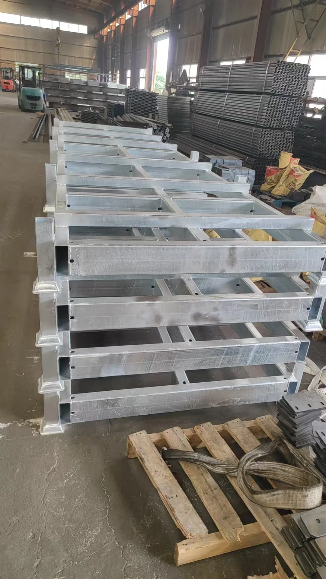
The completed product has conspicuous openings in the tube ends and on some side faces. These are not random punctures or fabrication damage.
They are deliberate galvanizing process and drainage openings for closed hollow sections.
6.1 Why Closed Tube Ends Create a Problem
When a hollow steel section is dipped in molten zinc, the zinc bath and processing solution must be able to enter and leave the internal cavity.
| Condition Inside a Sealed Hollow Section | Consequence |
|---|---|
| No vent or drain opening | Air, solution and zinc cannot circulate correctly |
| Trapped air | Incomplete or inconsistent internal zinc coverage |
| Trapped solution or zinc | Excess material remains inside after processing |
| No service drainage path | Rainwater entering the cavity cannot escape |
| Moisture retained inside | Increased risk of internal corrosion |
A closed tube may look protected on the outside while its internal surface remains vulnerable.
6.2 How the Openings Serve the Galvanizing Process
The openings allow the galvanizing bath and solution to flow into and out of the cavity, allowing zinc to reach and coat the internal surfaces.
| Functional Requirement | How the Openings Help |
|---|---|
| Vent the cavity during immersion | Allows trapped air to escape |
| Permit zinc and solution to circulate | Supports more consistent internal coverage |
| Allow excess material to drain | Prevents trapped zinc and solution inside the section |
| Protect the internal surface | Enables zinc coverage rather than leaving the cavity unprotected |
| Allow post-service drainage | Provides an escape path for rainwater that enters the tube |
6.3 Why Side Openings Are Also Used
The case review shows openings on the side faces as well as at the tube ends.
Side drainage is useful because a rack component may be installed or laid down in different orientations. A single opening at one end does not guarantee that water can escape in every position.
| Opening Location | Primary Purpose |
|---|---|
| Tube end | Vent and drain during galvanizing; provide a service drainage path |
| Side face | Allow trapped water to escape under different installation or storage orientations |
The opening positions should be approved in the fabrication drawing. They must provide adequate galvanizing access and drainage without unnecessarily weakening the section or creating unwanted sharp edges.
The holes are not defects. They are functional features that allow the hollow section to be galvanized internally and to release water after installation.
7. What a Hot-Dip Galvanized Surface Should Look Like
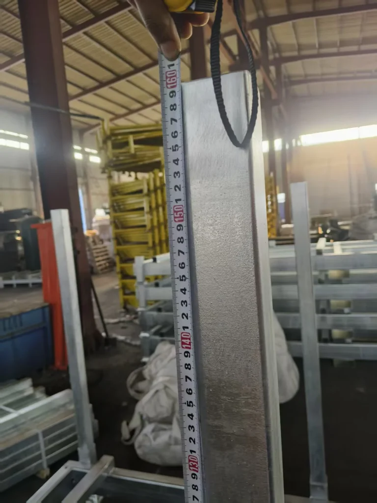
The production inspection includes close views of the completed galvanized columns.
| Visible Feature | Normal Explanation | Assessment |
|---|---|---|
| Dull, matte-grey surface | Characteristic appearance of a hot-dip galvanized finish | Expected |
| Mottled or spangled appearance | Result of the zinc-coating process | Expected |
| Small scattered surface marks or pits | Common local features of a galvanized surface | Assess against the coating specification |
| Bright, highly reflective finish | More characteristic of a decorative finish | Not normally expected for hot-dip galvanizing |
The purpose of hot-dip galvanizing is functional protection, not a uniform showroom appearance.
The production review also records the measurement of column height. This is an important check for a modular plug-in rack because small variations in component length can affect:
overall frame height;
socket engagement;
beam alignment;
squareness of the assembled rack;
and the final stacking condition.

8. Post-Galvanizing Cleaning and Plug-In Flexibility
A distinctive feature of a hot-dip galvanized plug-in rack is that the coating process can affect the product’s mechanical function.
During galvanizing, molten zinc enters the open tube. When it cools, small accumulations of zinc dross, lumps or internal residue may remain inside the cavity.
8.1 Effect on Plug-In Performance
| Condition | Effect on the Product |
|---|---|
| Zinc dross or lumps remain inside the tube | The column resists insertion and withdrawal |
| Excess zinc reduces the internal clearance | Insertion force becomes inconsistent |
| Operators apply excessive force | Local damage or an unsafe installation practice may result |
| Socket entry becomes unreliable | Assembly and disassembly take longer and become less repeatable |
| Internal residue is carefully removed | Columns can be inserted and withdrawn more smoothly |
The case therefore places particular importance on testing the plug-in and pull-out flexibility after galvanizing.
On a plug-in rack, internal zinc residue is not merely a cosmetic issue. It can directly affect whether the product performs the function for which it was designed.
8.2 What the Functional Test Should Confirm
The completed-product test should verify:
smooth column insertion into the socket;
repeatable withdrawal;
absence of excessive internal interference;
no sharp zinc projections that could damage the socket edge;
consistent operation between different columns;
and correct socket engagement after repeated assembly and disassembly.
The relevant production record should state the acceptance requirement rather than relying only on an informal visual demonstration.

9. The One-Degree Inward Pre-Tilt
The final production detail is the one-degree inward pre-tilt installed on the columns. It is not obvious in a catalogue drawing and reflects experience accumulated through repeated production of large plug-in tube racks.
9.1 The Problem: Columns Tilt Outward Under Load
The columns are installed in welded sockets. When the stored tube is placed inside the rack, it pushes outward against the columns.
The columns can therefore tilt away from the centerline.
| Consequence of Outward Tilt | Practical Effect |
|---|---|
| Top of the column moves outward | The loaded rack no longer presents a vertical working geometry |
| Material cannot be stacked square | Placement on top becomes difficult or inaccurate |
| Frame geometry changes under load | The rack no longer matches its intended assembled shape |
| Effect repeats during loading | The condition is introduced every time the rack is loaded |
| Unstable stacking | A load supported by leaning columns may become unstable |
9.2 The Solution: Start Slightly Inward
During assembly, the columns are installed with an inward pre-tilt of approximately one degree, adjusted according to column length.
Shims or packing are placed at the base to establish this angle.
| Stage | Column Condition | Purpose |
|---|---|---|
| During assembly | Column leans inward by approximately 1° | Establishes the designed pre-compensation |
| Before loading | Slightly inward of vertical | Prepares the rack for the load-induced movement |
| During loading | Stored tube pushes the column outward | The permitted clearance allows the column to move |
| After loading | Column returns to approximately vertical | The load-induced movement offsets the pre-tilt |
| During stacking | Working geometry is approximately vertical | Allows material to be stacked square and stable |
The technique depends on an appropriate clearance between the column and its socket. If the column is rigidly locked in place, the pre-tilt cannot compensate for the outward movement.
9.3 Why This Detail Matters
This is a small assembly adjustment with a direct effect on the customer’s experience. It was developed by observing how columns behaved after loading during repeated production of large plug-in racks.
The one-degree figure should not be applied indiscriminately to every rack. The pre-tilt must be established for the actual:
column length;
socket clearance;
loading arrangement;
material diameter and contact condition;
and assembly geometry.
The technique converts a load-induced defect into a designed pre-compensation: the rack is intentionally set slightly out of position while empty so that it reaches the intended position when loaded.
10. The Empty State: Transport Savings and Customer Storage
The plug-in construction allows the rack to be dismantled after the stored tube is removed.
The case review identifies two reasons for this compact state.
10.1 Lower Shipping Cost
For overseas customers, freight can represent a significant proportion of the delivered product cost. A rack shipped as separate components can use the available container volume more efficiently than a rack shipped with its entire frame permanently assembled.
10.2 Less Customer Storage Space
When the rack is not in use, it should not continue to occupy the same floor area as a fully assembled loaded rack. Removing the columns and beams allows the customer to store the components more compactly.
| Condition | Compactness Benefit |
|---|---|
| Empty rack awaiting shipment | Reduced freight volume and potentially lower transport cost |
| Empty rack at the customer’s facility | Reduced storage footprint during idle periods |
| Partial loading or unloading | Individual sections can be removed without dismantling unrelated areas |
| Repeated use | Plug-in construction allows the rack to be re-erected for later storage cycles |
The design principle is straightforward:
Meet the operating requirements first, then reduce transport space wherever doing so does not compromise the product’s function.
11. Packing and Shipment
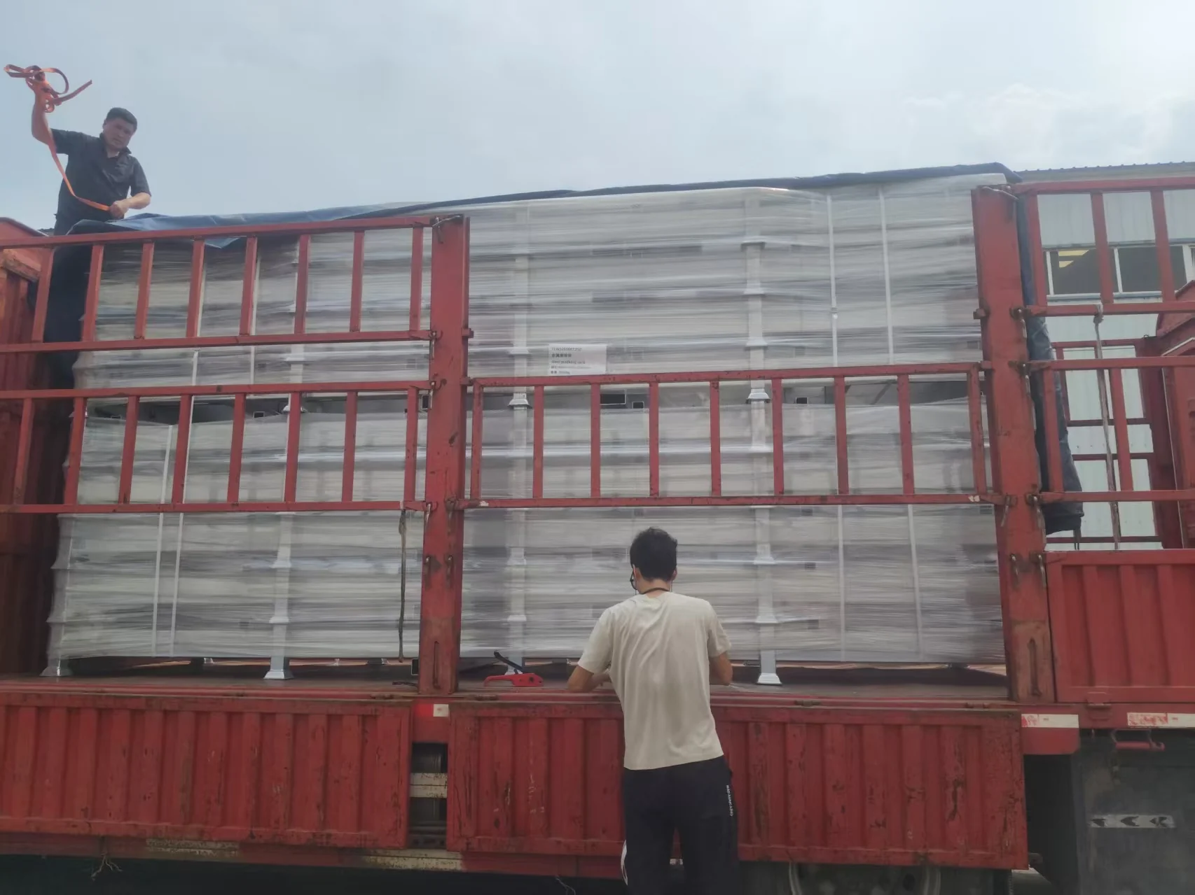
This was a relatively small batch, described in the review as nine units or sets. It was therefore shipped as loose cargo rather than as a full container load.
| Logistics Element | Recorded Arrangement |
|---|---|
| Return from galvanizing plant | Finished galvanized components returned to the Hebei factory |
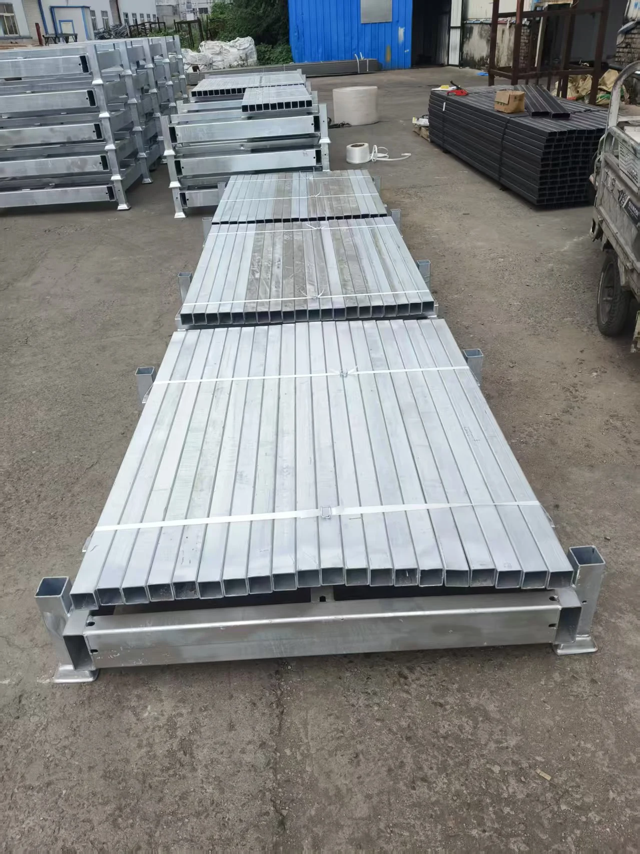
| Post-galvanizing packing | Columns packed in bundle form |
| Pre-shipment bundling | Columns bundled and secured on top of the rack bodies to reduce empty shipping space |
| Domestic transport | Road transport from the factory to the port |
| Export handling | Containerization at the port |
| Shipment type | Loose cargo for the relatively small batch |
| Production evidence | Post-production inspection, functional testing and packing records available |
Two practical lessons emerge from this arrangement.
First, packing must be planned after the galvanizing subcontractor has returned the actual components. The package dimensions depend on the real material received, not only on the theoretical production order.
Second, a plug-in rack contains different component types that travel differently:
the rack bodies or frames form the main packed units;
the removable columns can be bundled together;
and the combined arrangement can reduce unused container volume.
The final packing should always be confirmed against the component list, actual measurements and container-loading plan.
12. Recommended Inspection and Traceability Points
The following points are engineering recommendations based on the manufacturing processes described in the case. They are not additional claims made by the presentation.
| Production Stage | Recommended Check | Evidence to Retain | Acceptance Basis |
|---|---|---|---|
| Material receipt | Tube grade, section dimensions, wall thickness and material certificates | Incoming inspection record | Purchase specification and approved drawing |
| Frame fabrication | Socket position, beam alignment, weld quality and frame squareness | Fit-up and weld inspection record | Approved fabrication drawing |
| Galvanizing preparation | Drainage and vent openings present at tube ends and side faces | Pre-galvanizing photographs | Galvanizing drawing and process requirement |
| Post-galvanizing inspection | Coating appearance, local thickness, continuity and opening condition | Coating inspection report and photographs | Coating specification |
| Internal tube cleaning | No excessive zinc dross, lumps or sharp projections inside the columns | Cleaning and inspection record | Assembly and handling requirement |
| Plug-in flexibility test | Column insertion and withdrawal force and repeatability | Test record and video | Product functional requirement |
| Column height check | Length consistency across all columns | Measurement record | Approved drawing |
| Pre-tilt installation | Inward angle, shimming and base support | Assembly record and photographs | Assembly work instruction |
| Final assembly | Frame squareness, socket engagement, beam seating and plug-in security | Final inspection checklist | Approved assembly drawing |
| Pre-shipment inspection | Missing components, coating damage, packing condition and bundle securing | Packing list and release photographs | Shipping and acceptance requirements |
The presentation does not disclose specific coating standards, inspection frequencies, pre-tilt tolerances or column-length tolerances. Final acceptance must use the project’s approved technical documents.
13. Six Lessons from This Application
1. Start With the Storage Environment
The outdoor condition determined not only the coating but also the need for galvanizing and drainage openings. Corrosion protection was a system decision rather than a finish applied at the end.
2. A Heavy Static Load Can Produce a Different Design from a Lighter Dynamic Load
The 8 t base is never lifted. The 2 t upper levels are. Both cases must be evaluated independently, and one cannot be used as a substitute for the other.
3. Add Structure Where the Load Path Is Weakest
The third channel beam was the most visible design change. It improved the static capacity of the base while also increasing the dynamic stiffness of the forklift-handled levels.
4. Closed Sections Must Be Able to Vent and Drain
A sealed hollow tube cannot be galvanized internally and cannot release trapped rainwater. Deliberate openings are functional requirements, not manufacturing defects.
5. Galvanizing Changes the Mechanical Function of a Plug-In Rack
Zinc residue inside a column can directly affect insertion and withdrawal. Cleaning and flexibility testing must therefore be treated as part of the manufacturing specification.
6. Pre-Compensate for the Movement Caused by the Load
The one-degree inward pre-tilt converts an outward lean under load into a return toward vertical. It is a small detail that directly improves stacking and the customer’s daily operating experience.
14. Where This Solution Applies
This case provides a practical reference for:
outdoor tube and pipe storage;
long material requiring several support lines;
applications combining a heavy permanent base load with forklift-handled upper levels;
plug-in racks intended for repeated assembly and removal;
export projects where freight cost is a significant part of the delivered price;
environments requiring long-term corrosion protection;
and facilities where material is regularly stacked above the rack.
Conclusion
The outdoor tube-storage application demonstrates how customer conditions reshape an otherwise standard Derack product.
For this project, the main decisions were:
hot-dip galvanizing, with a recorded zinc-layer requirement of at least 40 microns for the intended outdoor environment;
deliberate galvanizing and drainage openings at tube ends and side faces, allowing the internal cavity to receive zinc coverage and release rainwater;
a third channel beam, added to the original two-beam arrangement to support the 8 t static base load and improve the stiffness of the forklift-handled upper levels;
post-galvanizing internal cleaning, so that the columns could be inserted and withdrawn smoothly;
a plug-in flexibility test, verifying the mechanical function of the finished galvanized product;
a one-degree inward column pre-tilt, allowing the outward force of the stored tube to bring the columns back toward vertical;
a dismantled empty configuration, reducing both shipping volume and the customer’s idle storage footprint;
and bundled packing of the removable columns, shipped by road to the port and then containerized.
The customer stores 8 tons of outdoor tube in a rack that must be galvanized, drained, emptied, shipped, re-erected and stacked—and every one of those requirements produced a specific design or manufacturing decision.
Send us the stored material length, the load on each level, the handling method and the storage environment. Derack plug-in tube racks allow the beam arrangement, galvanizing details and packing method to be specified around those conditions. Talk to the Steel Pallet team