
Uma única lista de bobinas pode abranger facilmente uma faixa de diâmetro de 2,7×. Um projeto documentado de distribuição de cabos listava 22 tipos de bobinas de Ø737 mm a Ø2.007 mm, com pesos de bobina de aproximadamente 500–3.000 kg e larguras de bobina dentro de uma faixa listada de 610–1.118 mm. Uma estante que coloca todas as bobinas em um único nível fixo não pode atender a essa lista: ao definir o nível para o tambor de Ø2.007 mm, a maior parte do volume acima das bobinas pequenas torna-se espaço morto; ao defini-lo para o tambor de Ø737 mm, o tambor grande simplesmente não pode ser carregado.
O layout usado naquele projeto não era uma única altura de prateleira, mas dois grupos de estantes da mesma família de estruturas — uma divisão por faixa de diâmetro. A seguir: como as bobinas foram agrupadas, o que muda entre uma faixa de dois níveis e uma faixa de um nível, por que uma estrutura auxiliar não é uma estante autoportante e como o passo de furos de 100 mm no montante é usado para definir a altura do suporte da bobina. Cada valor citado aqui é um valor de referência daquele projeto documentado, e não uma classificação universal Carack.
Por que uma única altura de prateleira não pode cobrir uma lista de bobinas de 737 mm a 2.007 mm
A cable drum occupies vertical space equal to its own diameter, plus the clearance a forklift needs to place the drum on the coil support and remove it again. Between Ø737 mm and Ø2,007 mm, the height requirement varies by about 1,270 mm, which is more than an entire usable level in a rack of this class. This is why the documented design did not standardize a single level height: the coil list was split first, and the support positions were then defined by group. Two other columns in the same list are just as important as the diameter. The coil weight — about 500–3,000 kg in the list — determines the selection of the support and the base. The coil width — 610–1,118 mm in the listed range — defines how much of the frame depth a drum occupies and how close two positions can be.
How to group cable drums into diameter ranges
The grouping starts from the coil list, sorted by diameter, with weight and width attached. The rule of thumb is simple: a bay is valid when all coils in it can sit on the same support spacing, with the same forklift entry, without the level above interfering. If one coil in a bay forces the level to be taller or the position wider, that coil belongs to the bay above it. On the documented list of 22 coils, the split produced two groups. The two-level group held four coil positions per frame unit for the smaller diameters. The one-level group held two coil positions per frame unit for the larger diameters. Both reference designs were approximately 3,002 mm tall. The reference main and auxiliary frame weights were 638 kg and 368 kg for one group, and 690 kg and 360 kg for the other. These numbers describe the two designs from that project; a different coil list produces different bays, different positions per frame unit, and different frame weights.
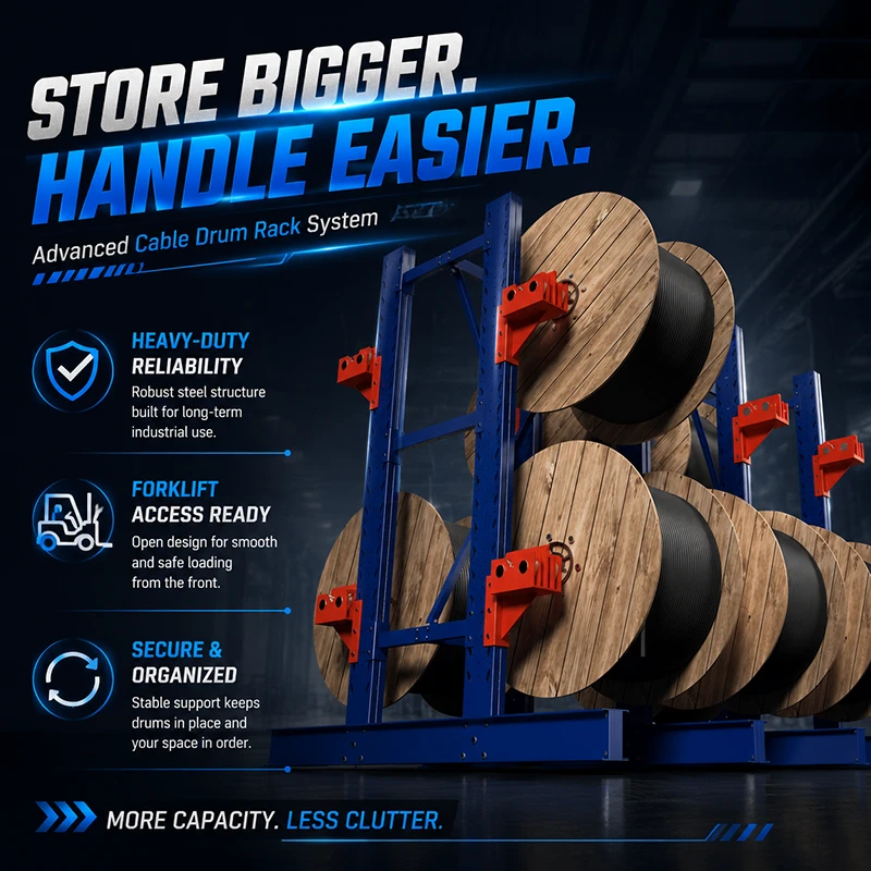
What changes between a two-level bay and a one-level bay
A faixa de dois níveis é o lado eficiente em espaço da divisão: tambores menores são empilhados, quatro posições por unidade de estrutura no design documentado, e a altura da estrutura é usada duas vezes. A faixa de um nível dá ao tambor grande o nível completo — duas posições por unidade de estrutura, sem suporte superior interferindo no carregamento, e sem a tentativa de espremer um segundo nível sob o topo da estrutura. Observe o que não muda: o grupo de um nível não é uma estante mais alta. Ambos os grupos de referência tinham cerca de 3.002 mm de altura, de modo que o que mudou foi o layout do suporte na mesma altura da estrutura, e não a altura da estrutura em si. Quando os dois grupos são comparados, compare as posições por unidade de estrutura e o corredor que a empilhadeira precisa, e não o contorno da estante.
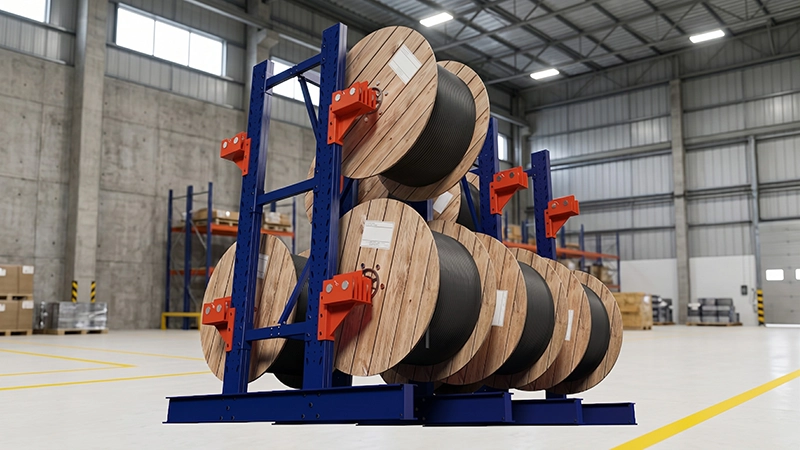
Por que uma estrutura auxiliar não pode ser instalada sozinha
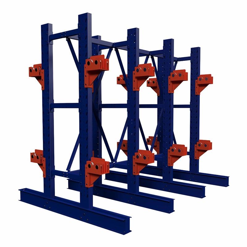
Uma baia Carack é construída como uma estrutura principal mais estruturas auxiliares opcionais. Nesse arranjo, a estrutura auxiliar não possui suporte próprio independente: ela depende do montante da estrutura principal e é integrada ao mesmo conjunto contraventado. No design documentado com múltiplas baias, uma estrutura principal mais duas estruturas auxiliares formavam a estante; as estruturas auxiliares acrescentavam posições de bobina, não acrescentavam uma coluna autoportante. Duas consequências práticas se seguem. Uma estrutura auxiliar não pode ser orçada como uma estante autônoma para uma ilha de armazenagem separada — essa ilha precisa de sua própria estrutura principal. E a posição da estrutura auxiliar, a conexão da base e o contraventamento têm de ser projetados em conjunto com a estrutura principal, e não adicionados depois que a estante está montada. Os pesos de estrutura de referência apontam na mesma direção: nos designs documentados, a estrutura principal tinha cerca de 638 kg e 690 kg, e a estrutura auxiliar cerca de 368 kg e 360 kg.
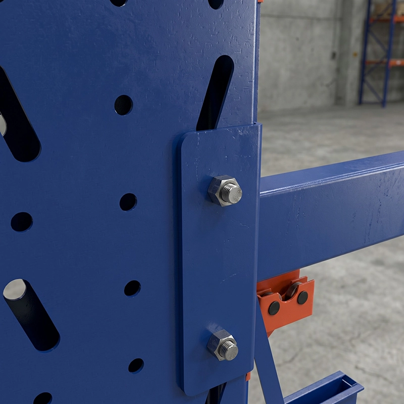
How to use the 100 mm hole pitch on the upright
The upright's dedicated profile is punched with mounting holes at 100 mm intervals, and this pitch is the adjustment increment for the coil support height. The sequence is: fix the diameter band first; find the lowest hole that gives the largest drum in the band the clear diameter and forklift entry it needs; then set the same position at every position in that band so the group stays level. The pattern is a fixed 100 mm pitch, not continuous adjustment, so a support lands in the nearest valid hole rather than at a calculated exact millimeter. This is normally sufficient because the level is designed around a band, not around a single coil. The same upright also carries both levels of a two-level band, which is why the pitch is a feature of the structure rather than an accessory. If the coil list changes, the supports can be re-set on the same upright; the structure does not need to be replaced.
Where the diameter-band approach does not apply
The split described above is a planning method with clear limits, and it is worth making them explicit before a coil list is sent for quotation.
- Bands are built from a list. If inventory turns over every few weeks, the bands go stale and need to be checked again before ordering.
- If cable has to be paid off the drum on site, that is a roller-bearing support decision with its own clearance requirement, separate from the band split. Carack is a fixed steel storage structure, not an automated cable carousel, cable winding machine, or cantilever reel stand with pay-off.
- If a drum is taken off the rack and transferred to a mobile trolley, the fork clearance and the support geometry for that move must be confirmed, not assumed.
- Outdoor storage requires a corrosion-control finish agreed with the quotation and an operational decision on rain exposure; the rack is not automatically an outdoor product.
- No universal load capacity, steel grade, safety factor or anchoring requirement should be read from this article. Capacity, finish and anchoring are confirmed for the specific configuration in the quotation or drawing.
Where this rack layout fits
- Cable distribution centre whose reel list mixes small and large diameters
- Buffer storage in a cable factory between production, testing and dispatch
- Electrical and power equipment warehouse with a defined reel list and forklift access
- Long warehouse row where one master frame is extended with slave frames
- Outdoor cable yard, where a corrosion-control finish is specified for the configuration
Perguntas frequentes
How do I know how many diameter bands my reel list needs?
Sort the list by diameter, then test two limits: what fits between two support levels and what needs a level of its own. On the documented 737–2,007 mm list this produced exactly two bands — a two-level band with four positions per frame unit and a one-level band with two positions per frame unit. The number of bands follows the list; there is no fixed number. The test for each band is whether its largest drum still passes the support above it and still leaves usable forklift entry.
Can I order only the slave frame and use it as a separate rack?
No. The auxiliary structure relies on the main structure's amount for support and is part of the same braced assembly, so it is an extension of a main structure rather than a self-supporting unit. If you need a second separate storage island, budget that island with its own main structure.
Does the 100 mm hole pitch let me move the support height by 100 mm whenever I want?
Support positions are set in 100 mm increments because that is the installation hole pitch. That is sufficient to set one level for a defined drum diameter range and to reset it later if the coil list changes, but it is not continuous adjustment and by itself does not guarantee clearance. Drum diameter, drum width, support geometry, and forklift entry still need to be checked for the configuration.
Send the coil list — diameter, weight, and width of each drum — together with the handling equipment and aisle you have, and the banding, positions per frame unit, and frame combination can be worked out for your location instead of borrowed from the reference design above.
Precisa de uma Solução de Armazenamento Personalizada?
Fale diretamente com nossos engenheiros técnicos. Oferecemos projetos estruturais gratuitos, avaliações de catálogos de alta capacidade e orçamentos rápidos para B2B.
Solicite um Orçamento Agora →