
MYTRACK Production and Testing: 2,222 mm Internal Dimension, Empty-State Folding and Container Loading
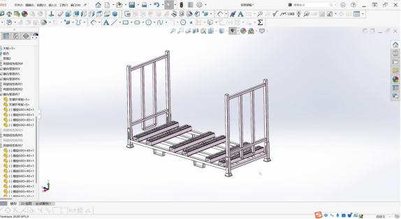
Production case study of the MYTRACK foldable stillage: 2,380 mm outer envelope, 2,222 mm internal opening, 8 units per 40 ft high-cube container, empty-state folding, chamfered stacking corners and steel-lined rubber strips.
MYTRACK Production and Testing: 2,222 mm Internal Dimension, Empty-State Folding and Container Loading
An 80-rack production run of the MYTRACK folding stillage, documented from fabrication to physical test: a 2,380 mm outer envelope, a 2,222 mm maximum internal opening, eight units per 40 ft high-cube container, empty-state folding, chamfered stacking corners, flared stacking horns and a steel-lined rubber strip.
MYTRACK Production and Testing: 2,222 mm Internal Dimension, Empty-State Folding and Container Loading
The previous MYTRACK case study explained how a specially designed rack used controlled deformation to meet three core customer requirements. This production review follows the product through fabrication and physical testing at the manufacturing facility in Hebei.
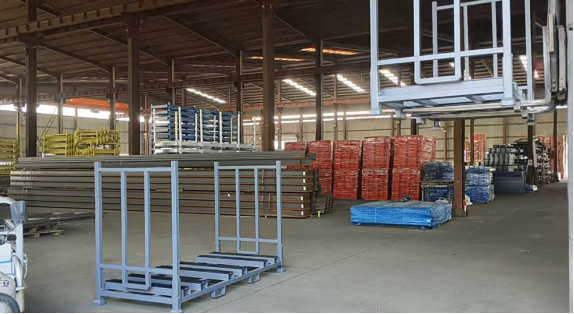
The finished MYTRACK was not treated as a routine production order. Because its dimensions, folding behaviour and stacking function were closely related to the customer’s operating and shipping requirements, the entire production run was documented through photographs and video.
The review focused on four practical questions:
How could the rack provide the largest possible internal dimension without reducing the number of units loaded into each container?
Could the rack fold into a stable empty-state arrangement and then be stacked without interference?
Would the stacking details allow the operator to align the units easily and keep the completed stack vertical?
Would the finished product perform correctly during forklift handling and stacking?
The most restrictive requirement was not simply the rack’s size. It was how many units the customer could load into one container—and every dimensional decision was made around preserving that quantity.
1. Production and Testing at a Glance
| Item | Recorded Specification or Test | Significance |
|---|---|---|
| Product | MYTRACK | Special folding and stacking configuration |
| Overall outer dimension | 2,380 mm | Governs the product footprint and container utilization |
| Maximum internal dimension | 2,222 mm | Largest internal opening offered within the recorded outer envelope |
| Difference between outer and internal dimensions | 158 mm in total across the outer envelope | Allows for the frame structure and required clearances |
| Stored board relationship | Approximately 30–40 mm smaller than the internal dimension | Provides practical insertion and withdrawal clearance |
| Container loading quantity | 8 units per 40 ft high-cube container | Possible only at the recorded dimensions and height |
| Production quantity | 80 racks | The complete batch was photographed and recorded |
| Empty-state configuration | Side upright sections can be folded inward; folding panels can be lowered | Allows compact stacking when the rack is empty |
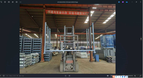
| Forklift handling test | Forklift-lifted rack photographed and video recorded while being moved | Confirms the completed product’s handling configuration |
| Stacking test | Units stacked with wooden boards above and below the rack | Verifies the stacking and supporting arrangement |
| Maximum stacking test | Maximum stacking configuration photographed | Records the highest demonstrated arrangement |
| Stacking corner | Chamfered geometry | Allows the locating pin to slide into position |
| Stacking horn | Flared or bell-mouth entry | Provides operator tolerance and limits lateral movement after stacking |
| Rubber strip | Steel-lined rubber strip | Prevents an automatic nailer from piercing through the rubber |
| Folded-panel retention | Retaining element along the lower edge | Prevents the stored board edge from protruding through the opening |
| Final alignment | Good overall verticality, with upright centres aligned through the stack | Confirms the repeatability of the stacking arrangement |
| Production records | Photographs and videos retained for internal retrieval | Provides an as-built and testing reference for the team |
These are project-specific production references. The 2,222 mm internal dimension and eight-unit container loading quantity are not universal MYTRACK specifications and must not be applied to another configuration without recalculation.

2. The Dimension Problem: Maximizing Internal Space Without Losing Container Capacity
The production review began with a point that had not been described in detail during the earlier design presentation: the actual dimensions were tightly constrained by the customer’s shipping requirements.
The finished rack had an overall outer dimension of 2,380 mm. Within that envelope, the maximum internal dimension was 2,222 mm.
2.1 The Two Critical Dimensions
| Dimension | Recorded Value | Functional Significance |
|---|---|---|
| Overall outer dimension | 2,380 mm | Determines the product footprint and the number of units that can be loaded |
| Maximum internal dimension | 2,222 mm | Determines the usable opening for the stored board |
| Total difference | 158 mm | The combined difference between the outer envelope and internal opening |
| Stored board | Approximately 30–40 mm smaller than the internal dimension | Allows the board to enter and withdraw without binding |
| Maximum offered internal dimension | 2,222 mm | Confirmed by the presenter as the limit that could be provided |
The 158 mm figure is the total difference across the outer envelope, not the thickness of one side. The two sides, structural members and required clearances together account for that difference.
2.2 Why the Internal Dimension Stopped at 2,222 mm
If the customer’s containers had unlimited loading space, a larger internal dimension might have been desirable. The stored board would then have been able to occupy more of the available opening.
However, increasing the internal dimension also required increasing the outer dimension. That would directly reduce the number of MYTRACK units that could be loaded into each container.
| Design Option | Benefit | Commercial Consequence |
|---|---|---|
| Increase the internal dimension | A larger stored board could be accommodated | The outer dimension increases and fewer units fit in each container |
| Retain the 2,380 mm outer dimension | Container-loading quantity is preserved | The internal dimension cannot be increased beyond the available frame capacity |
| Maximize the internal dimension within the fixed outer envelope | The largest practical opening is provided without sacrificing loading quantity | The finished dimension reaches 2,222 mm |
The design sequence was therefore clear:
fix the outer dimension so that the required number of units could be loaded;
determine the largest internal dimension that the frame could provide within that envelope;
size the stored board with suitable operating clearance.
The internal dimension was not an independent preference. It was the outcome of a container-loading constraint.
2.3 The 30–40 mm Clearance
The stored board was close to the internal opening, with a difference of approximately 30–40 mm.
| Measured Relationship | Practical Purpose |
|---|---|
| Board smaller than the internal opening | Enables insertion and withdrawal |
| Clearance maintained on both sides | Prevents binding when the board is loaded or removed |
| Internal opening governed by the frame | A larger board would require a larger outer envelope |
| Relationship based on the actual board arrangement | Must be recalculated if the board size or support method changes |
This clearance should be reviewed whenever the stored material changes. A board with different dimensions, a different support arrangement or a different removal direction may require a revised opening.

3. The Container-Loading Constraint
The reference loading arrangement was a 40 ft high-cube container, into which eight MYTRACK units could be loaded individually.
| Loading Parameter | Recorded Value | Result |
|---|---|---|
| Container type | 40 ft high-cube | Reference project container |
| Loading quantity | 8 MYTRACK units | Achievable only at the recorded dimensions and height |
| Effect of increasing the overall dimension | Larger product footprint | Fewer units would fit in the container |
| Effect of increasing the height | Larger stacked envelope | Fewer units would fit in the container |
| Freight consequence | Higher freight cost per unit | Directly affects the customer’s delivered cost |
| Prohibited design outcome | Reducing the number of units for dimensional convenience | Confirmed as unacceptable during the design process |
3.1 Why Eight Units Matter
Container-loading quantity is not only a packing concern. For an export order, it directly affects the freight cost allocated to each unit.
| Loading Outcome | Commercial Effect |
|---|---|
| 8 units in one container | Freight cost is distributed across the maximum possible quantity |
| 7 units in one container | Freight cost per unit increases |
| Loading quantity left undecided | Product dimensions and quotations cannot be finalized reliably |
| Loading quantity fixed early | Packing plans, quotations and delivery schedules can be coordinated |
For an export rack, the container can act as a design boundary. It determines the maximum practical product size at the intended commercial margin.
3.2 The Forklift Channel Was Almost Touching the Adjacent Unit
During the review, the forklift-channel opening was checked in the stacked condition.
It was confirmed that the channel opening of one unit was positioned immediately next to, and almost touching, the side of the neighbouring unit.
| Checked Feature | Recorded Observation |
|---|---|
| Forklift-channel position | Adjacent to the neighbouring unit’s side |
| Actual product versus theoretical model | The relationship matched the theoretical arrangement |
| Interference | No conflict in the demonstrated configuration |
| Design implication | The dimensional arrangement was close to its maximum allowable packing limit |
This was not a comfortable clearance margin. It was a tightly controlled fit that had to be verified on the physical product.

4. The Height Trade-Off
The overall height was another dimension that could not be selected in isolation.
| Height Decision | Advantage | Disadvantage |
|---|---|---|
| Make the rack taller | Potentially more vertical capacity | Reduces the number of units that can be stacked and loaded |
| Make the rack shorter | Potentially more units in the container | May create interference when the folding panels or doors are lowered |
| Final selected height | Preserves the eight-unit loading quantity | Maintains clearance in the empty, folded-down condition |
4.1 The Empty Condition Required Independent Verification
The folding function was not an additional feature added after the loaded configuration had been completed. It changed the geometry of the product and therefore required its own dimensional check.
| Operating Condition | Required Result |
|---|---|
| Rack loaded | Panels and upright sections remain in their working positions |
| Rack emptied | Side upright sections can be folded inward and the folding panels can be lowered |
| Folded-down panels | Must not interfere with the frame or adjacent structure |
| Empty rack stacked | Folded members must clear the corresponding side member |
| Completed stack | No contact or interference that compromises the intended arrangement |
In the demonstrated stacked condition, the lowered member rested on the corresponding side member rather than fouling it.
This clearance is why the final height could not simply be reduced to gain more container space.
A rack that works correctly when loaded must still be designed for the condition in which it is empty, folded and stacked.

5. Production and Physical Testing Record
The complete production run was documented to provide an as-built reference and to verify the special folding and stacking functions.
| Test or Record | What Was Performed | Evidence Retained |
|---|---|---|
| Overall completed product | Completed MYTRACK units inspected | Production photographs |
| Forklift handling simulation | Forklift lifted the rack and moved it in the raised position | Photographs and video |
| Wooden-board stacking | Wooden boards placed below and above the stacked rack | Production photographs |
| Maximum stacking | Highest stacking arrangement demonstrated | Production photographs |
| Complete batch | All 80 racks photographed together | Batch-level production record |
| Empty-state folding | Side upright sections folded inward when empty | Operator demonstration video |
| Folding-panel clearance | Panels lowered in the empty condition and checked for interference | Physical-product verification |
| Empty-state stacking | Multiple folded units stacked together | Stacking demonstration |
| Chamfer function | Locating pin allowed to slide along the chamfered corner | Physical-product demonstration |
| Rubber-strip installation | Rubber strips fixed to the arched plates | Installation photographs and video |
| Loaded stacking operation | Two racks brought together after loading | Stacking-operation demonstration |
| Final verticality | Completed stack inspected from multiple directions | Production photographs and video |
5.1 The Full 80-Rack Batch Was Recorded
The photographs covered the complete batch of 80 racks.
| Reason for Batch Documentation | Value |
|---|---|
| Special production configuration | Establishes an as-built reference for the product |
| Consistency across the run | Shows that multiple units were manufactured to the same operating principle |
| Folding and stacking verification | Provides a reference for how the units should be deployed |
| Future installation and service use | Allows the approved photographs and videos to be retrieved when required |
| Design feedback | Demonstrates how the theoretical details behaved on physical units |
The production images and videos were also archived in the product information system, where they can be retrieved when required.

6. The Chamfer at the Stacking Corner
One of the most important physical details was the chamfer at the stacking corner.
6.1 How the Chamfer Works
When one unit is stacked onto another, a locating pin must enter the corresponding positioning feature.
The chamfer provides a transition surface that allows the pin to slide into position instead of meeting a sharp, abrupt square edge.
| Corner Geometry | Stacking Behaviour |
|---|---|
| Sharp square edge | The locating pin meets an abrupt corner and may resist entry |
| Chamfered edge | The pin can slide along the transition and seat in the intended position |
| Effect of the chamfer | Easier engagement, improved repeatability and reduced point loading on the locating feature |
The chamfer was visible in the physical product, although the first workshop demonstration did not capture the locating pin sliding along it particularly clearly. The reviewer subsequently showed the feature in greater detail.
6.2 A Small Detail with a Large Operating Effect
A chamfer may appear insignificant when viewed from a distance, yet it directly influences whether stacking is repeatable across an entire production batch.
| Benefit | Practical Result |
|---|---|
| Provides a guiding surface | The locating pin is directed into the correct position |
| Reduces sensitivity to small alignment differences | The operator does not need perfect positioning on every unit |
| Limits abrupt contact | Reduces the risk of damaging the pin or edge during engagement |
| Supports repeatable stacking | Each unit is more likely to seat in the same relative position |
The stack becomes consistent because every unit is guided by the same geometry—not because each level is manually adjusted after stacking.
7. The Rubber Strip and Its Steel Backing Liner
The upper sections of the MYTRACK use rubber strips fixed together with the middle and lower arched plates.
7.1 Installation Method
The rubber-strip installation was also demonstrated in the production footage.
| Component | Recorded Arrangement |
|---|---|
| Rubber strip | Positioned against the arched plate assembly |
| Arched plates | The middle and lower arched plates are used together with the strip |
| Fixing points | Four fixing points on each arched plate |
| Installation technique | The worker holds the strip in position while making the fixings |
| Existing detail | The fixing arrangement matches the rubber-strip installation used on the related arched-plate structure |
7.2 Why the Rubber Strip Contains a Steel Liner
The rubber strip included a steel plate liner inside it.
The purpose was to prevent an automatic nailer or stapler from passing completely through the rubber during installation.
| Condition Without a Steel Liner | Consequence |
|---|---|
| The automatic nailer penetrates through the rubber | The strip is pierced and weakened |
| Multiple fixing points pass through the strip | The rubber can split or pull away from its intended position |
| Fixing quality becomes inconsistent | The strip may loosen, deform or lose its contact function |
| The service condition becomes difficult to control | The finished product may not retain the material consistently |
| Benefit of the Steel Liner | Effect |
|---|---|
| The fixing tool meets steel rather than passing through rubber | The rubber remains intact |
| The strip is held securely at the fixing point | Fixing quality becomes more consistent |
| The rubber retains its full cross-section | Contact and damping performance are protected |
| Production rework is reduced | Less risk of replacing a damaged rubber strip |
This was both a production-quality decision and a protection of the finished product’s service performance.

8. The Retaining Stop on the Folded Panels
The MYTRACK’s folded-panel detail was inspired by an existing feature used on the fabric rack.
8.1 The Similar Problem
The fabric rack uses a U-shaped retaining element to prevent fabric from slipping through an opening when the rack is folded.
Although a wooden board is much less flexible than fabric, the same basic issue can occur:
the board sits slightly forward in the folded position;
its edge becomes visible through the gap;
and the edge may catch or project outside the rack profile during handling.
8.2 The MYTRACK Solution
A retaining stop was added along the lower edge of the folded section.
| Product | Material at Risk | Retaining Detail | Result |
|---|---|---|---|
| Fabric rack | Flexible fabric | U-shaped retaining element | Prevents fabric from falling through the folded opening |
| MYTRACK | Wooden board or panel | Lower retaining bar | Prevents the board edge from protruding through the gap |
| Common operating principle | Stored material must remain contained | Positive edge retention | Reduces edge exposure and catching during handling |
The solution adapted an established product detail to a different material rather than ignoring a relatively small but visible operating problem.

9. The Flared Stacking Horn
The production review also highlighted the flared, bell-mouth form of the stacking horn.
9.1 Why the Flare Was Necessary
The presenter explained that the flared geometry gives the operator tolerance during the stacking operation.
| Corner or Horn Geometry | Operator Experience |
|---|---|
| Straight, parallel-sided entry | The operator has almost no tolerance for small positioning errors |
| Flared, bell-mouthed entry | The widening upper section provides a forgiving alignment space |
| Result | The stacking operation becomes significantly easier and less frustrating |
The flare was therefore introduced as an operator-facing tolerance feature rather than simply as an aesthetic shape.
9.2 The Flare Also Helps Restrict Lateral Movement
After the units were stacked, the upper, narrower part of the horn contacted the corresponding upright.
| Stage | Geometry | Function |
|---|---|---|
| Before stacking | Wide bell-mouth entry | Makes alignment easier and provides tolerance |
| During engagement | Locating features guide the units into position | Helps establish repeatable alignment |
| After stacking | Narrow upper section contacts the upright | Reduces lateral movement or rotation of the stacked units |
The flared feature therefore performs two functions:
it makes the operation easier while the operator is positioning the units;
it helps restrain the completed stack once the units are engaged.
The flare solves two problems with one geometry: it makes alignment forgiving and helps keep the finished stack in position.
10. Stacking and Verticality
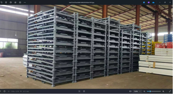
After the loaded units were brought together, the reviewer walked around the stack and inspected its alignment.
| Verification Item | Recorded Result |
|---|---|
| Overall straightness | Good |
| Overall verticality | Good |
| Upright alignment | The uprights follow the direction of the chamfered stacking corner |
| Alignment between levels | Each upright aligns with the centre of the upright immediately above or below |
| Visible rotation or offset | No significant lateral displacement was observed |
10.1 Why the Geometry Supports Vertical Alignment
The final alignment result follows directly from the chamfered stacking corner.
| Geometric Feature | Consequence Through the Stack |
|---|---|
| Chamfer guides the locating pin | Each unit seats in a repeatable position relative to the unit below |
| The same geometry is used at every level | Alignment is not based on an accidental or manual adjustment |
| Small deviations do not simply accumulate | The locating features continue to guide each subsequent unit |
| Upright centres remain aligned | The completed stack maintains good overall verticality |
The result is a self-correcting stacking arrangement. Every level is guided into the same relationship, allowing the full stack to remain visually straight.
The completed stack is vertical because the same guiding geometry is repeated at every level.

11. Functional Test Summary
The following table summarizes the physical tests and observations presented in the production review.
| Test | What Was Verified | Recorded Result |
|---|---|---|
| Forklift handling | Rack lifted and moved in the raised position | Operation demonstrated and recorded |
| Batch completeness | Complete production batch | 80 racks photographed |
| Wooden-board stacking | Boards placed below and above the stacked rack | Arrangement demonstrated and recorded |
| Maximum stacking | Maximum stack configuration | Configuration photographed |
| Empty-state folding | Side upright sections folded inward when empty | Demonstration completed |
| Folding-panel clearance | Lowered panels checked for interference | Folded member rests on the corresponding side member |
| Empty-state stacking | Folded units stacked together | Arrangement demonstrated |
| Forklift-channel adjacency | Channel position relative to the neighbouring unit | Adjacent and nearly touching, with no interference |
| Chamfer function | Locating pin engagement | Pin allowed to slide along the chamfer |
| Rubber-strip installation | Strip fixed to arched plates | Four fixing points shown on each arched plate |
| Steel liner protection | Resistance to automatic-nailer penetration | Steel-backed rubber construction confirmed |
| Retaining-stop function | Control of the board edge in the folded condition | Lower retaining element prevents edge exposure |
| Loaded stacking operation | Two units brought together after loading | Flared horn demonstrated as an alignment aid |
| Lateral restraint | Narrow upper horn engaging the upright | Helps restrict movement after stacking |
| Verticality | Alignment of uprights throughout the stack | Good overall verticality and level-to-level alignment |
The public production review does not disclose specific loads, deflection limits, dimensional tolerances, fastener specifications or formal test acceptance values. Those requirements must be verified through the project’s approved technical documentation.
12. Six Lessons from the MYTRACK Production Review
1. Start with the Shipping Constraint
The number of units loaded into a container determined the practical outer dimension and height. The internal opening was then maximized within that envelope.
2. The Empty State Is a Separate Design Condition
The folded panels, folded upright sections and empty-state stacking arrangement each required their own clearance checks. A product that works when loaded may still fail when folded.
3. Small Geometric Features Have Large Operational Effects
The chamfer enables repeatable engagement and supports the vertical alignment of the stack. The flared horn makes positioning easier and helps restrain lateral movement.
4. Soft Components Must Be Protected During Installation
The steel liner inside the rubber strip prevents the automatic nailer from piercing through the rubber. The detail protects both manufacturing quality and finished-product performance.
5. Adapt Proven Details Instead of Ignoring Small Problems
The retaining stop on the folded panel was based on an existing fabric-rack solution. Reusing the underlying principle helped control a real edge-exposure and catching problem.
6. Verify the Physical Product
The model established the intended geometry, but the physical units confirmed the folding clearance, pin engagement, rubber-strip installation, stacking tolerance and final verticality.
13. Where These Production Practices Apply
This review provides a practical reference for:
specially dimensioned export racks;
products with an important empty-state folding requirement;
racks that must maximize their internal opening within a fixed shipping envelope;
repeated stacking and unfolding operations;
containers where loading quantity has a direct commercial impact;
racks using rubber strips, locating pins or flared stacking guides;
production teams responsible for maintaining as-built evidence;
and any project where a physical prototype is needed to validate the final manufacturing detail.
Conclusion
This MYTRACK production review demonstrates how a special application is transformed from an engineering concept into a tested physical product.
Dimensioning Under a Container Constraint
The overall outer dimension was fixed at 2,380 mm to preserve the customer’s container-loading quantity. Within that envelope, the maximum internal dimension was 2,222 mm, and the stored board was sized approximately 30–40 mm smaller than the opening.
Eight Units in a 40 ft High-Cube Container
The reference loading arrangement allowed eight MYTRACK units to be loaded individually into a 40 ft high-cube container. This quantity depended on the recorded height, folding clearance and overall dimensions. The forklift channel of one unit was confirmed to sit immediately beside the neighbouring unit’s side.
Folding and Empty-State Stacking
When empty, the side upright sections could be folded inward and the folding panels lowered. The final height was selected so that the folded-down condition did not interfere with the frame or the adjacent structure. The folded member was confirmed to rest on the corresponding side member.
Functional Manufacturing Details
A chamfer at the stacking corner allows the locating pin to slide into position and helps every level align consistently. A flared, bell-mouthed stacking horn gives the operator tolerance during placement, while its narrow upper section contacts the upright after stacking and helps restrict lateral movement. The steel-lined rubber strip prevents the automatic nailer from piercing through the rubber, and the lower retaining bar prevents the board edge from protruding through the folded opening.
Physical Verification and Traceability
The complete run of 80 racks was photographed. Forklift handling, wooden-board stacking, the maximum stacking arrangement, empty-state folding, rubber-strip installation, loaded stacking and final verticality were demonstrated on the physical product. The photographs and videos were archived in the product information system for later retrieval.
The product was shaped by the shipping method, and then proved by handling the real thing: folded flat, stacked, lifted, loaded and inspected for alignment from every side.
If your internal opening, folded height or stacking tolerance is being set by the container you ship in, send us the board or panel size, the container type and the number of units you need per load. We will calculate the outer envelope and the folding clearance for your configuration, and confirm the stacking geometry before production. Send your dimensions to the Steel Pallet team