
Line-side storage is a capacity decision, not a visual merchandising exercise. The right number of wire mesh containers at a station depends on the station takt, the replenishment batch, the usable quantity in each container, the time required to bring the next load, and the way operators can reach the material. One extra cage can narrow a route; one missing cage can stop production.
This planning method applies to Stbox collapsible wire mesh containers used for industrial parts and work-in-progress (WIP). It does not replace the approved drawing, load plan, or site safety review. Treat dimensions, capacity, stacking height and gate orientation as project inputs—not universal promises.
Start with consumption, not the container count
First define the station’s actual consumption rate. If a station uses R parts per hour, and the replenishment route needs L hours from request to the next usable load, the minimum parts buffer is:
Required parts buffer = R × L
Then define the usable quantity C per wire mesh container. C is not necessarily the geometric volume. It is the quantity that can be loaded without damaging parts, blocking the drop gate, exceeding the approved load, or making manual picking unsafe. The first planning estimate is therefore:
Minimum containers in the replenishment window = ceiling((R × L) ÷ C)
For a batch-fed process, also test the supplier’s batch quantity B. If one delivery arrives with B parts, use ceiling(B ÷ C) containers for that delivery, then check whether the station consumes them before the next delivery. A result that works only on average but fails during a changeover is not a workable line-side plan.
Convert the calculation into a rotation plan
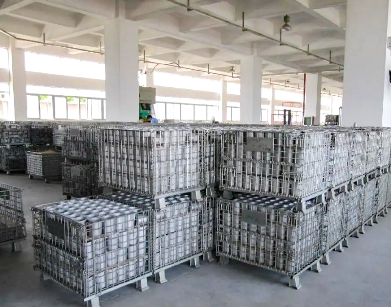
The station normally needs more than the quantity being consumed. Map the operating states: one container being picked, one container waiting to be picked, one container being replenished or inspected, and any container held for changeover or quality segregation. Do not add a fixed “standard safety cage.” Instead, measure the delay and frequency that create each state.
- High-frequency replenishment: a smaller batch may work if the route is dependable and the aisle remains clear.
- Long replenishment lead time: the live rotation must cover consumption during that delay; calculate it from the measured route time.
- Frequent changeovers: size by the largest simultaneous part-family requirement, not by the average daily output.
- Variable fill levels: set a maximum usable quantity for each part, especially where mesh contact or mixed components create damage or sorting risk.
Stbox supports this rotation model because the same industrial storage cage can be handled by forklift or pallet jack in documented configurations, while a half-drop gate gives access to lower-level parts without unloading the full cage. The gate is a flow aid, not permission to reach through an unstable stack.
Let stacking limits constrain the answer
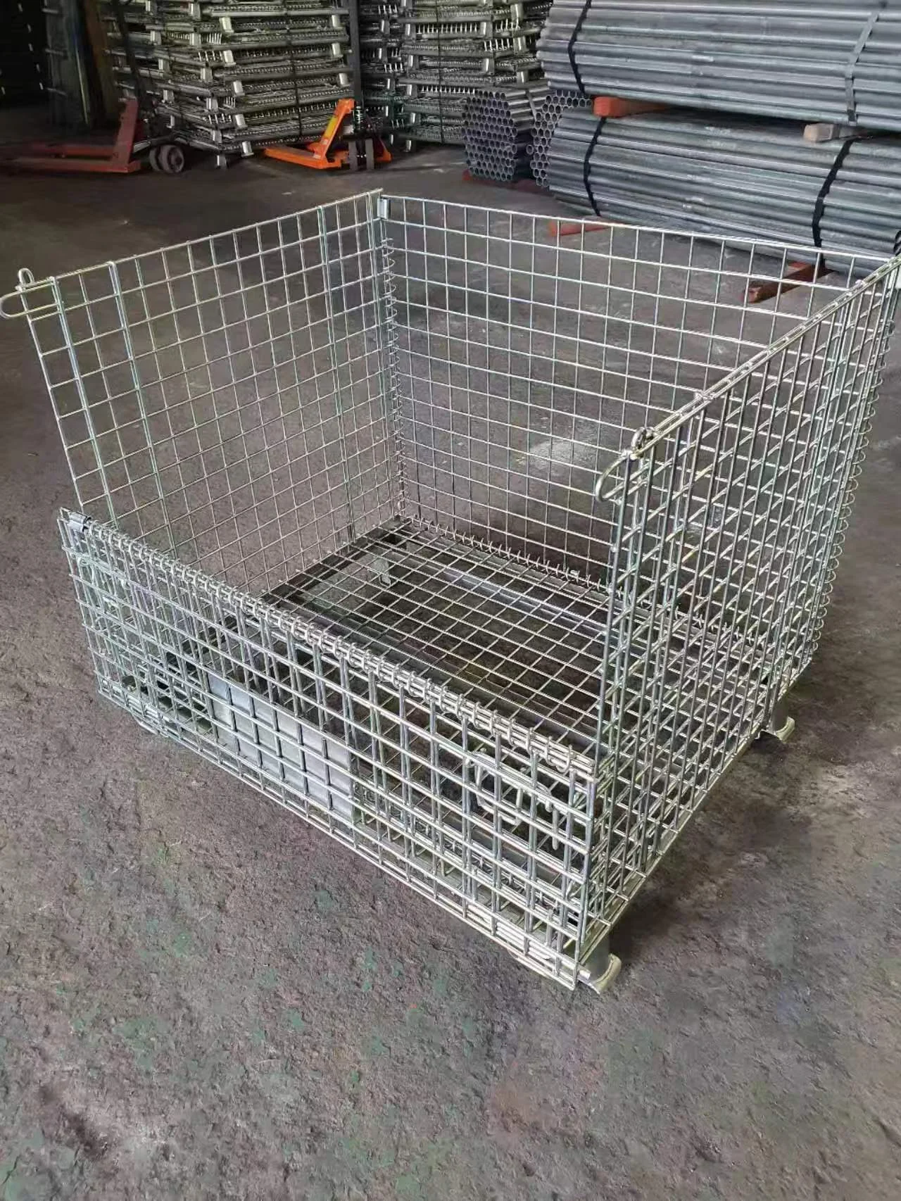
After calculating the live container count, test the physical storage plan. If the approved project stack limit is S containers high, the minimum floor positions for vertical storage are ceiling(N ÷ S). That is only a floor-space calculation. At the line side, operators may need the accessible container at one-high, so the theoretical saving from stacking may not be available.
For the documented 13967 project configuration, the table lists an 800 × 1200 × 890 mm cage, 1,000 kg dynamic load, and stacking of no more than four tiers with each upper cage limited to 500 kg. These figures must stay tied to that project drawing. Before releasing a stack, verify that the feet are fully seated, the forklift moves smoothly, and the actual load at every level complies with the approved plan.
Match the gate direction to the aisle
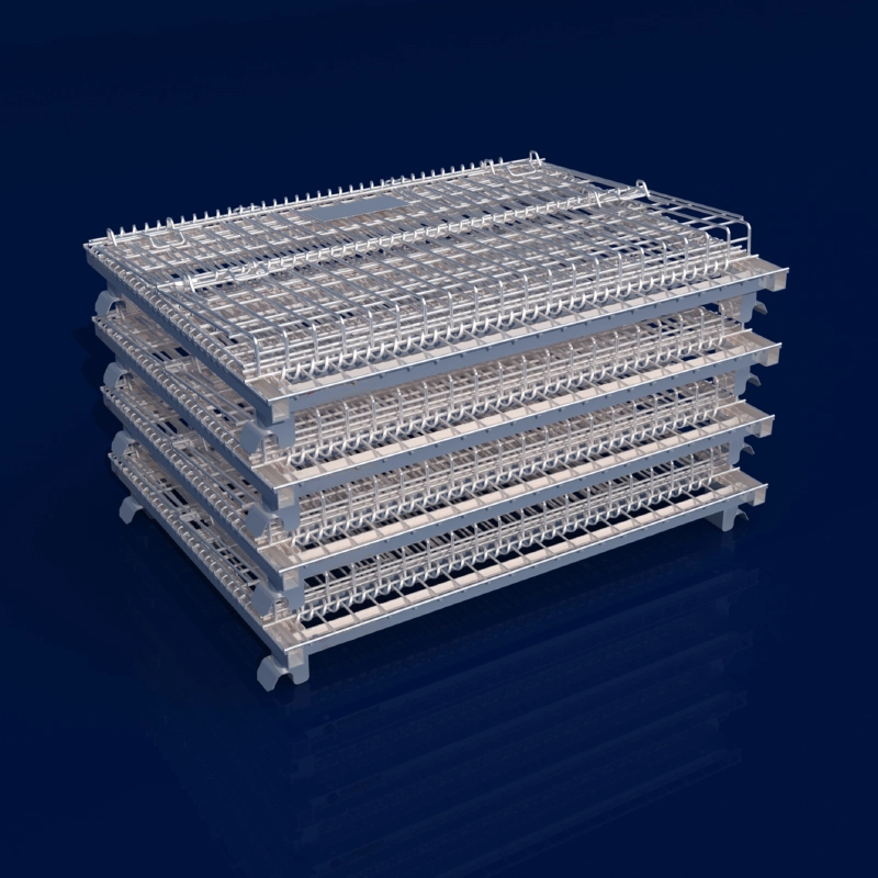
Opening direction and channel width are coupled decisions. Draw the container footprint, the gate swing or drop path, the operator standing zone, the pallet-jack or forklift approach, and the adjacent equipment envelope on the same layout. The usable line-side width is the available width after subtracting the container footprint and the access envelope required by the site’s EHS and material-handling rules.
The 13967 request places the opening on the 800 mm side, but the final gate orientation and terminology require drawing confirmation. Do not infer that orientation from a product photograph. If the gate faces the station, picking is direct but the container may project into the operator route. If it faces the replenishment aisle, delivery access may improve but manual picking may require repositioning. When two-sided access is needed, confirm that the selected design actually provides it.
Use the narrowest practical configuration only after a trial with the real pallet jack, part carton, operator posture and neighboring station. A mathematically sufficient number of cages is still wrong if the half-drop gate cannot open fully or the handling equipment cannot approach squarely.
Check the handling interface before freezing the quantity
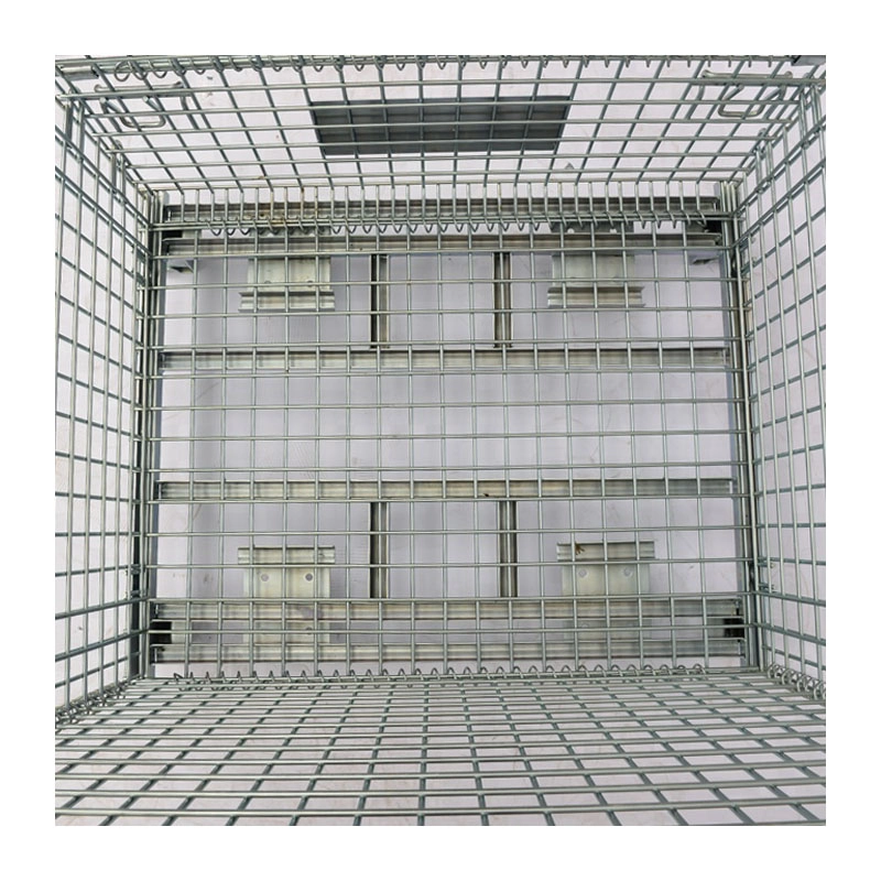
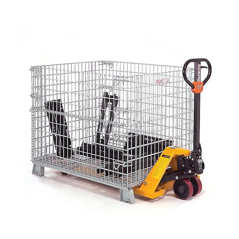
Confirm fork entry, pallet-jack access, turning space, floor condition and the route’s actual handling sequence. The Stbox image record shows pallet-jack lifting and a reinforced channel-steel base, but a visual reference does not replace a project-specific handling confirmation. For small or precision parts, specify whether a PP hollow-board liner is needed to limit rubbing, dust or loss through the mesh. For security-sensitive material, evaluate a lid; for movement over the shop floor, evaluate the caster variant with brakes. These options change the usable workflow and may change the quantity or footprint.
A practical request for a line-side quote
Send the station takt or hourly consumption, part quantity per batch, usable fill per container, replenishment lead time, changeover frequency, gate-side preference, available aisle width, handling equipment, load per cage and required stack condition. The supplier can then separate the calculated live rotation from the floor-layout constraint and confirm which dimensions, reinforcement, finish and accessories belong to the selected Stbox drawing.
Not sure how many cages your line-side buffer needs?
Share your takt time and replenishment batch. We can help convert them into a wire mesh container configuration plan for review.
Need a Custom Storage Solution?
Speak directly with our technical engineers. We offer free structural designs, heavy-duty catalog evaluations, and quick B2B price quotations.
Request a Quote Now →